
You are using an out of date browser. It may not display this or other websites correctly.
You should upgrade or use an alternative browser.
You should upgrade or use an alternative browser.
KT motor controllers -- Flexible OpenSource firmware for BMSBattery S/Kunteng KT motor controllers (0.25kW up to 5kW)
- Thread starter casainho
- Start date
geofft
10 kW
Are you sure the ground line is continuous from the battery to the controller ground?
geofft
10 kW
Yes.
So when powered up do you see the supply voltage across the controller -ve and R63?
So when powered up do you see the supply voltage across the controller -ve and R63?

geofft
10 kW
Ok, you're missing the supply voltage on R63, without this the controller will not power up.
This voltage is fed from the display when you power up, this is what you are missing.
It seems you either have a break in this connection somewhere or the display is faulty. It's possible to unplug the display and replace it with a bypass plug to power on the controller, I'll give details on this tomorrow if needed.
Over and out for me tonight..

geofft
10 kW
Thanks mate I'll drop you a message tomorrow.
Display isn't connected at the moment it's on the bike.
....if you want to run the controller without a display connected you'll need to link pins 1-2 on the controller display connector. This links the Bat+ back to Vin input (via R63) to power up the cpu and fet driver circuits, etc. Some bypass plugs also linked pins 3-5 together, I think this grounds the RX line, I'm guessing to prevent any noise on the line interfering with the controller.
Hey bud,
It has done "something" ...
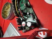
So testing between -ve controller and LEFT leg of C63 I get 58.8v now
Right leg 47.8v.
-------
Between +ve controller & LEFT leg of LM317 reg 34.66v
+ve controller right leg of LM317 reg 9v
Between -VE & LEFT leg of LM317 reg 22.5V
Between -VE & RIGHT leg of LM317 reg 48.1v
-------
Between +ve & LEFT leg of 78M05 reg 26v
Between +ve & RIGHT leg of 78M05 reg 52v
Between -ve & LEFT Leg of 78M05 reg 24v
Between -ve & RIGHT leg of 78M05 reg 4.99v
____ where does that mean we're at ? It looks promising...
It has done "something" ...
So testing between -ve controller and LEFT leg of C63 I get 58.8v now
Right leg 47.8v.
-------
Between +ve controller & LEFT leg of LM317 reg 34.66v
+ve controller right leg of LM317 reg 9v
Between -VE & LEFT leg of LM317 reg 22.5V
Between -VE & RIGHT leg of LM317 reg 48.1v
-------
Between +ve & LEFT leg of 78M05 reg 26v
Between +ve & RIGHT leg of 78M05 reg 52v
Between -ve & LEFT Leg of 78M05 reg 24v
Between -ve & RIGHT leg of 78M05 reg 4.99v
____ where does that mean we're at ? It looks promising...
geofft
10 kW
That's a fairly random set of voltage measurements there, you really just need to know if the o/p's of the two voltage regs are correct. Best keep your voltage measurements related to ground (-ve) not the +ve line.
The 7805 looks like it's correct at 5v, the o/p of the LM317 is the centre pin, this should be around 15v.
I'm guessing that's probably gonna be ok, so presuming all else is well you should be good to go...?
The 7805 looks like it's correct at 5v, the o/p of the LM317 is the centre pin, this should be around 15v.
I'm guessing that's probably gonna be ok, so presuming all else is well you should be good to go...?
geofft
10 kW
No, that's not correct, that voltage is too high. I think the issue is that the max permissible input voltage for an LM317 appears to be 40v - you're well outside that and trying to operate it outside it's working range.
You need to get that i/p voltage down below 40v, you can do this by increasing the value of R63. I can't get my head around the maths at the moment but a value somewhere near 400 ohms might be a good starting point.
Hopefully the excess voltage from the LM317 hasn't damaged anything else in the controller - what was it's quoted operating voltage?
Quoted op is for 48v batt but I doubled checked and can use 52v batt.
Fets are good to 72v
Caps 63v.
Adding a bigger resistor of the correct amount in place of C63 or adding one in series maybe ?
I have some spare C63 resistors here if that can help anything.
Fets are good to 72v
Caps 63v.
Adding a bigger resistor of the correct amount in place of C63 or adding one in series maybe ?
I have some spare C63 resistors here if that can help anything.
geofft
10 kW
Adding a bigger resistor of the correct amount in place of C63 or adding one in series maybe ?
I have some spare C63 resistors here if that can help anything.
Whatever method you choose, best to bear in mind that these resistors get bloody hot at the best of times, probably even more so with your increased voltage, so make sure you use high wattage types.
geofft
10 kW
Left to right
16v 17v 40.5V
Is that still ever so slightly too high ?
Probably near enough to give it a test, though I'd be inclined to drop it a little more at some point... :wink:
geofft
10 kW
Any idea what that could be ?
I think that without a display connected to communicate assist levels, speed limits, etc, the software will run in whatever mode it defaults to under those conditions. I've no real idea what those defaults are, possibly what you are experiencing at the moment.
My next step would be to fully connect the display with your settings set up and test again - hopefully you'll get a better result... :wink:
Whey !!! I've sorted it !!!
All hooked up boom it's working!!
Private me your PayPal and I'll buy you a few hot toddys or whatever you like haha
Appreciate your guidance I've actually learnt a hell of a lot.
I do love KT controllers, won't be moving from them now with having them schematics.
All hooked up boom it's working!!
Private me your PayPal and I'll buy you a few hot toddys or whatever you like haha
Appreciate your guidance I've actually learnt a hell of a lot.
I do love KT controllers, won't be moving from them now with having them schematics.
Update !!!
It just craps out when it wants to.
Reconnecting battery to controller kicks it back in.
Not a clue where to go from here.
Got a new one coming in next few days but feels like I've been defeated. GRRR !!!
I have a decent knowledge about electronics but nothing like you have geoff.
" so it gives power then when it wants to controller just stops giving power when it wants to & throttle just stops " reconnecting batt XT60 to controller XT60 it comes back then full throttle it picks up then shuts it self off:
Something crapping out. I've built my own battery and it's been solid for months. It's not the battery.
Could it be the BMS ?
Checked every fet prior; desoldering; charging each fet via diode mode with multimeter; discharging with a finger touch via middle pin they are all good im certain of that.
Not a clue where to move forward with it from here.
Any thing ring a bell with your knowledge of these controllers ?
geofft
10 kW
To be honest I've not much more idea than yourself with this, I hope you're not overestimating my electronics abilities... 
It sounds like the controller may be reacting to some kind of voltage excursion (maybe over/under voltage) or possibly a hardware issue with battery/controller/bms.
I think I'd start by bypassing the bms and running directly from the battery, to rule out a bms issue.
If it's still playing up maybe ride with a voltmeter connected to the battery to get some idea what the battery voltage is doing when it fails.
Also remember that you're operating the LM317 at it's upper limit, could this be overheating and going into thermal shutdown? Maybe increase R63 still further to reduce it's input voltage a bit further.
If all else fails, try it with your new controller when it arrives to rule out a controller issue. That's all I can think of at the moment, if anything else pops into my head I'll post it up.
Got some 5W resistors coming tomorrow.
I am more or less certain everything battery side / BMS is
Good as that's been working flawless for months.
What's the ideal voltage I want to pull INPUT of LM317T down too ? Would you say about 35v ? This should bring output & adjust to around 14-15v if I've calculated it right.
I think a 470 Ohm & 220 Ohm should bring it down to around 35v ish.
It would make sense thermal shutdown is kicking in on LM317T dropping the 5V line so the throttle craps out.
geofft
10 kW
I am more or less certain everything battery side / BMS is
Good as that's been working flawless for months.
As long as you're sure.....!
What's the ideal voltage I want to pull INPUT of LM317T down too ? Would you say about 35v ? This should bring output & adjust to around 14-15v if I've calculated it right.
There's plenty of info online about LM317's - yes, around 30-35v should be ok. Anywhere between 20-40v should see it regulate to around 15v.
It would make sense thermal shutdown is kicking in on LM317T dropping the 5V line so the throttle craps out.
If the LM317 shuts down you would lose all the internal supplies so the controller would shutdown completely. I'm not convinced that this is the issue, but it's certainly worth eliminating.
This is crazy haha
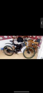
I've upgraded the phase lines from the motor with better lugs for a block connector to controller.
I've also shorted ground to the RX line on from LCD connector with +ve & blue signal also shorted from LCD connector and it's perfectly working.
No LCD connected with at the moment I'm not assed about, I just want to go to the chippy on my bike and not walk
But yeah I've done 15 miles today and it's been absolutely sound as a pound.
I'm so happy
Without you mate directing me bud I wouldn't have known where to start !!
Attachments
Similar threads
- Replies
- 129
- Views
- 47,609
- Replies
- 2
- Views
- 3,642