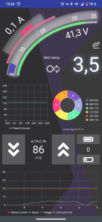
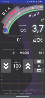
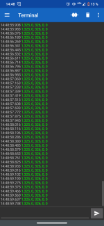
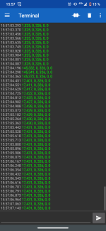
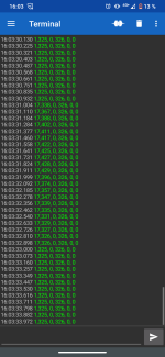
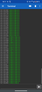
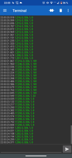
KT motor controllers -- Flexible OpenSource firmware for BMSBattery S/Kunteng KT motor controllers (0.25kW up to 5kW)

stancecoke

100 kW
Joined
Aug 2, 2017
Messages
1,697
While spinning: (1 | 34)
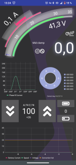
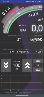
While still: (1 | 17)
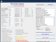
Have you read the wiki carefully?

34 decimal is 100010 binary (exactly the given example in the wiki ;)), that means:
  1. in torquesimulation and pedaling faster than ramp end
  2. overspeed and power output is being ramped down
So check your gear ratio, wheel circumference and your speed limits.

regards
stancecoke
 
Last edited:

Angrubean

10 mW
Joined
Aug 28, 2022
Messages
20
Have you read the wiki carefully?

34 decimal is 100010 binary (exactly the given example in the wiki ;)), that means:
  1. in torquesimulation and pedaling faster than ramp end
  2. overspeed and power output is being ramped down
So check your gear ratio, wheel circumference and your speed limits.

regards
stancecoke
Thank you for your reply stancecoke.

I didn't know that the second number in BlueOsec also was a control state.
But there's a slight problem, (1 | 17) is shown when the wheel (that the DD motor is mounted on) isn't spinning, and (1 : 34) while it's spinning.
No matter if I pedal or not. My speed limit is set to 50 km/h and I doubt that I can spin the wheel over 50 km/h by hand 🤣

Would be great if you helped me out with this one. Is there something I'm missing?
I'll double check the settings you've given me and reply with the result.
 

Angrubean

10 mW
Joined
Aug 28, 2022
Messages
20
So I have flashed the controller with new parameters.

I've set the speed limit to 100 km/h on every occasion (offroad ,no pas, limit)

I've also checked my wheel circumference and set it to 2230 in the software.

I also counted my magnets and divided them by 2 as in the wiki. Which results in 23 pole pairs/gear ratio.
1681645707631.png
I powered on the controller with everything hooked up and pushed the throttle, but nothing happened. Everything is as it was before.

(Pictures with pas and with throttle)
 

Attachments

  • Screenshot_20230416-132457.png
    Screenshot_20230416-132457.png
    421.2 KB · Views: 7
  • Screenshot_20230416-132445.png
    Screenshot_20230416-132445.png
    404.3 KB · Views: 6
  • Screenshot_20230416-132418.png
    Screenshot_20230416-132418.png
    399.6 KB · Views: 4
  • Screenshot_20230416-132411.png
    Screenshot_20230416-132411.png
    397.6 KB · Views: 5
  • 1681645707681.png
    1681645707681.png
    122.4 KB · Views: 6
Last edited:

stancecoke

100 kW
Joined
Aug 2, 2017
Messages
1,697
Hm, you pictures show a duty cycle of 255, this means full power. So something's really wrong. I'm not familiar with the BluOSEC App. Please flash in diagnostics mode post the output. Does the wheel block, if you operate the throttle? Then you have a wrong phase- and hall wire combination...
 

Angrubean

10 mW
Joined
Aug 28, 2022
Messages
20
Hm, you pictures show a duty cycle of 255, this means full power. So something's really wrong. I'm not familiar with the BluOSEC App. Please flash in diagnostics mode post the output. Does the wheel block, if you operate the throttle? Then you have a wrong phase- and hall wire combination...
Unfortunately it doesn't seem to be that easy, the wheel spins freely while on full throttle, should I do something while in diagnostics? Like spin the wheel, push the throttle or pas?

Here's a clean output when the controller isn't connected to anything.
 

Attachments

  • Screenshot_20230416-144859.png
    Screenshot_20230416-144859.png
    391.8 KB · Views: 5
Last edited:

stancecoke

100 kW
Joined
Aug 2, 2017
Messages
1,697
should I do something while in diagnostics?
Push the throttle, then second column should change.

Code:
ui16_control_state, (uint16_t) uint32_current_target, PAS_is_active, ui16_BatteryCurrent, ui16_sum_torque, (uint16_t)uint32_torquesensorCalibration);
 

Angrubean

10 mW
Joined
Aug 28, 2022
Messages
20
Push the throttle, then second column should change.

Code:
ui16_control_state, (uint16_t) uint32_current_target, PAS_is_active, ui16_BatteryCurrent, ui16_sum_torque, (uint16_t)uint32_torquesensorCalibration);
Doesn't even flinch. (Keep in mind, the controller is only connected to the battery, hc-05 and throttle at the time of diagnostics).
 

Attachments

  • Screenshot_20230416-155707.png
    Screenshot_20230416-155707.png
    394.8 KB · Views: 4
  • Screenshot_20230416-160334.png
    Screenshot_20230416-160334.png
    392.5 KB · Views: 4

stancecoke

100 kW
Joined
Aug 2, 2017
Messages
1,697
But the log is OK. The controller reacts to the throttle as expected. Connect the motor and try again, the 4th column should change with the throttle then also.
 

stancecoke

100 kW
Joined
Aug 2, 2017
Messages
1,697
Hm, seems like the PWM output is not enabled. You should check the state of the variable uint_PWM_Enable. I don't know, if the BluOsec App has this parameter in the Debug Panel. If not, you can edit this line of the code to
Code:
                printf("%u,%u, %u, %u, %u, %u\r\n", ui16_control_state, ui16_setpoint, ui16_motor_speed_erps, ui16_BatteryCurrent, uint_PWM_Enable, ui16_momentary_throttle);
Then in the 5th column should appear a 1.

regards
stancecoke
 

Angrubean

10 mW
Joined
Aug 28, 2022
Messages
20
Hm, seems like the PWM output is not enabled. You should check the state of the variable uint_PWM_Enable. I don't know, if the BluOsec App has this parameter in the Debug Panel. If not, you can edit this line of the code to
Code:
                printf("%u,%u, %u, %u, %u, %u\r\n", ui16_control_state, ui16_setpoint, ui16_motor_speed_erps, ui16_BatteryCurrent, uint_PWM_Enable, ui16_momentary_throttle);
Then in the 5th column should appear a 1.

regards
stancecoke
 

Attachments

  • Screenshot_20230416-192031.png
    Screenshot_20230416-192031.png
    432.1 KB · Views: 3
  • Screenshot_20230416-192050.png
    Screenshot_20230416-192050.png
    446.5 KB · Views: 3

stancecoke

100 kW
Joined
Aug 2, 2017
Messages
1,697
?! What is your line 194 in your main.c now?! You have untervoltage now, (2048) didn't you attach the battery?
 

Angrubean

10 mW
Joined
Aug 28, 2022
Messages
20
?! What is your line 194 in your main.c now?! You have untervoltage now, (2048) didn't you attach the battery?
Sorry!

The Java tool loaded up the wrong config and I didn't seem to notice. Here is the output with the right config. Still 0.
 

Attachments

  • Screenshot_20230416-194554.png
    Screenshot_20230416-194554.png
    396.4 KB · Views: 4

stancecoke

100 kW
Joined
Aug 2, 2017
Messages
1,697
Sorry, again: what is your line 194 now. You don't seem to have edited the line according to my suggestion, otherwise, the momentary throttle would appear in column 6...
 

Angrubean

10 mW
Joined
Aug 28, 2022
Messages
20
Sorry, again: what is your line 194 now. You don't seem to have edited the line according to my suggestion, otherwise, the momentary throttle would appear in column 6...
1681669407370.png1681670519037.png
1681670327444.png

You're right!
SDCC doesn't seem to find uint_PWN_Enable. And therefore nothing was flashed onto the controller.
Also, The throttle momentary could be seen in BlueOsec, it should be visible on my previous screenshots.
 

stancecoke

100 kW
Joined
Aug 2, 2017
Messages
1,697
uint_PWN_Enable is not exported from the ACAsetPoint.h :-(
Sorry, I think you have to go too deep into the code, to fix that.

You can try to read the register directly:

Code:
 printf("%u,%u, %u, %u, %u, %u\r\n", ui16_control_state, ui16_setpoint, ui16_motor_speed_erps, ui16_BatteryCurrent, TIM1->CR1 & TIM_CR1_CEN, ui16_momentary_throttle);
 

Angrubean

10 mW
Joined
Aug 28, 2022
Messages
20
uint_PWN_Enable is not exported from the ACAsetPoint.h :-(
Sorry, I think you have to go too deep into the code, to fix that.

You can try to read the register directly:

Code:
 printf("%u,%u, %u, %u, %u, %u\r\n", ui16_control_state, ui16_setpoint, ui16_motor_speed_erps, ui16_BatteryCurrent, TIM1->CR1 & TIM_CR1_CEN, ui16_momentary_throttle);
1681674895128.png
1681674970444.png1681674970476.png
It seems that "TIM_CR1_CEN" doesn't exist. I suppose you meant "TIM1_CR1_CEN"?
 

Angrubean

10 mW
Joined
Aug 28, 2022
Messages
20
This is the output with the following code
1681675449554.png
 

Attachments

  • Screenshot_20230416-220324.png
    Screenshot_20230416-220324.png
    399.8 KB · Views: 4

stancecoke

100 kW
Joined
Aug 2, 2017
Messages
1,697
I see, you print out the duty cycle now, too. Everything seems to be OK on software side. So I guess, there is a hardware fault. Do you have a scope for checking the Pwm signals?
 

Angrubean

10 mW
Joined
Aug 28, 2022
Messages
20
I see, you print out the duty cycle now, too. Everything seems to be OK on software side. So I guess, there is a hardware fault. Do you have a scope for checking the Pwm signals?
Sadly no, I don't have access to an oscilloscope. Do you know any other way of debugging? The PCB looks fine, there's at least no visible damage. May it be an incompatibility of IC's? I've searched through this thread and I couldn't find anyone with a 3PEAK TP104 op amp. The sensor should be compatible because of its frequent appearance, It also matches with the "spec sheet" of the s06s.

And that's everything I currently can think of that may cause this. Any ideas on what I should do next? I do have access to a "ST LM324" op amp that should be similar to the others in this thread. Would it possibly make a better fit for this firmware? Or doesn't it matter?
 

stancecoke

100 kW
Joined
Aug 2, 2017
Messages
1,697
Do you know any other way of debugging?
You can check the voltage on the gate pins of the MOSFETS. On low side, they should be about 5V, on high side a little higher than half the battery voltage, when the contoller is switched on, but no throttle is operated. (center aligned PWM has 0.5 duty cycle when the current is zero) But be careful with the probes, don't produce magic smoke ;)
The opamp model has nothing to do with the problem, I guess...
 

Angrubean

10 mW
Joined
Aug 28, 2022
Messages
20
You can check the voltage on the gate pins of the MOSFETS. On low side, they should be about 5V, on high side a little higher than half the battery voltage, when the contoller is switched on, but no throttle is operated. (center aligned PWM has 0.5 duty cycle when the current is zero) But be careful with the probes, don't produce magic smoke ;)
The opamp model has nothing to do with the problem, I guess...
No magic smoke on my watch;). But there is a slight problem, the MOSFETs marked with blue(K150E09NE) are the only ones that receive any gate voltage, which also is strange. You said that the low side should have 5v, and the high should be at about half the battery voltage. Now the only reads I got from the blue was 13v that doesn't seem right as my battery supplies 40v.
 

Attachments

  • IMG_20230417_164027026~2.jpg
    IMG_20230417_164027026~2.jpg
    1.2 MB · Views: 5
Last edited:

stancecoke

100 kW
Joined
Aug 2, 2017
Messages
1,697
OK, so it's a nine FET...
The blue ones are the high side FETs?! The 13V should be the output voltage of the LM217. You could check the voltage on the PWM processorpins directly, this should be 2.5v exactly and standstill with no load. (5V @ 0.5 duty cycle)
 

Angrubean

10 mW
Joined
Aug 28, 2022
Messages
20
OK, so it's a nine FET...
The blue ones are the high side FETs?! The 13V should be the output voltage of the LM217. You could check the voltage on the PWM processorpins directly, this should be 2.5v exactly and standstill with no load. (5V @ 0.5 duty cycle)
By following these notes bmsbattery_s06s_controller_hardware/S06S.Txt at master · KingQueenWong/bmsbattery_s06s_controller_hardware
And this pinout
1681752604826.png
I could read 2.5v on all of the PWM high pins(26, 27 ,28), and 3.5v on all the PWM low pins(20,21,22). With the throttle disconnected.
 
Last edited:
Top