KT motor controllers -- Flexible OpenSource firmware for BMSBattery S/Kunteng KT motor controllers (0.25kW up to 5kW)

Um...speaking of which, dumb question but somewhere in these 5000 thread replies, is there a list for P1-5 and C1-14 where there is a layman's explanation for all parameters and more importantly, what the typical input for those parameters are.
No idea, but if you open the Github repository and navigate to display.c, then scroll down to about line 200, you'll see what the controller expects to receive from the LCD. There you can witness which parameters actually get assigned.

P1 - P5, C1 - C5, C12 - C14.

I haven't looked into where these variables end up or if they match the LCD, but feel free to explore for yourself.
1686595069646.png
 
but what functionality do I loose?
you loose a lot of unimportant and cryptish P and C settings on the LCD, you win a lot more features to fine tune your system by the Java GUI and/or the BluOSEC app. Just read the wiki. 🤷‍♂️
The C and P parameters are assigned to variables in the code, but nothing is done with this variables, excepting speedlimit and wheel size.
 
Hi, for now I have completed my Project (add Torquesensor to my Shengmilo MX05). I've done this 2.5 years ago with my Fiido M1.
Hub Drive 48V Bafang G020 500 and I`m on the Master Branch (not X4 because I don`t need Throttle or regen) .

1686925071302.png

Changes in Source
Delete Line 195 in ACAcomons.c (ui16_momentary_throttle = (uint16_t) map(ui8_adc_read_throttle(), ADC_THROTTLE_MIN_VALUE, ADC_THROTTLE_MAX_VALUE, 0, SETPOINT_MAX_VALUE); //read in recent throttle value for throttle override)

throttleMomentary was not Zero (Can`t adjust it even also not with higher Throttle min (ADC_THROTTLE_MIN_VALUE)) and it is running in the Function "Without PAS" that`s why the current Target was 0,2.
With this Change I can not even say the feeling is better or not by riding (I don't notice any difference :) ).

1686925696818.png

BTW
motorspecificAngle was adjusted with Bike lift up and full Throttle if it reach Speedlimit it show the correct CorrectionVal with that i adjust the Angle.

Next Weeks i will test and hopefully not burn the Hub down ;)

Sorry for my bad english but my german is "badder" :unsure:
 
Last edited:
Sorry forget , I use S06S and Torque Sensor Erider T9 from pswpower .
I'm considering to set the Function Assist Lvl Affects Throttle.
It cuts the max Current A by Assist Level then I can save Akku Power .
 
Last edited:
Good Morning,

I want to understand the Phase Current Value Setting and also what should/could I set for Battery/Phase Current , if I have a S06S Controller Rated Current 10A and Max Current 20A . (People stated they have burned their Hub Drive and always the Question was ,How high did you set Phase Current, so I think thats important ).

If i look in the Code I saw the Var (I`m a noob :) setpoint_old > 0 (//Limit Current Phase) and I didnt find where this is set ?

Sorry if this are dump Questions and was answered before .
 
Hiya,

I have a DYU D3F (a 14" mini-e-bike; the handlebar folds down), it has a direct drive motor in...really "as" the rear wheel (the magnets are basically directly part of the wheel, no gearing or freewheeling mechanism), and I'm trying to get this KT24/36ZWSRD-TS02G controller (rated 10A input, 20A phase current, if i read this info plate right) (PCB says "KT-6S5-C") with this firmware to run it nice.

And yes it was a ZWS controller, so I've modified it to have an ACS711 sensor -- i designed a little breakout board and had JLCPCB make and assemble that for me - it's the +-15.5A ACS711 _plus_ a 1milliohm shunt resistor across that to give it a range exceeding 20A (but the absolute current value would need to be calibrated if that was needed - if i understood right the firmware only needs the zero crossing point?).

I put in a 2200 ohm resistor on the main PCB (on the signal line of the ACS711, it had empty pads for that) as that is what the schematic I found showed, but I'm not 100% if that was a good idea (or whether it would work better just directly), or whether an RC filter would be better (the PCB also had pads for a capacitor to ground, if i thought right... could also be resistor divider but i think that's not necessary).

Onto my problem: currently with interpolation enabled, it runs smooth-ish (there's a rough spot somewhere near 15 ERPS) but more depressingly has a max no load speed (wheel in the air, this is all i can do for testing right now) of about 80 ERPS (which if i computed it right, would be like 20 km/h - if you want to go computing, there were 30 changes of the lowest bit of the hall state in a rotation of the wheel, but i think you only count one of the edges, so a "gear ratio" of 15 and a wheel circumference of about 1055mm).

If i disable interpolation, the running sound is a little bit rougher, but it reaches a max speed of about 170 ERPS (which is quite fast).

I did look into (but didnt touch much) adjusting the motor angle (or such), if that would be something to do with this (honestly I'm not sure, and annoyingly i "only" have a PC with serial port, not the bluetooth dongly, so i don't know what the app would say), i did try this:
Code:
// before while(1) in main.c:
        printf("%03d %03d %03d %03d %03d %03d\r\n",
            ui8_s_hall_angle4_0, ui8_s_hall_angle6_60, ui8_s_hall_angle2_120,
            ui8_s_hall_angle3_180, ui8_s_hall_angle1_240, ui8_s_hall_angle5_300);
// in the very slow loop
                 printf("\r%03d %03d %03d %03d %03d %03d",
                 (uint16_t) uint8_t_hall_case[0], (uint16_t)uint8_t_hall_case[1],
                 (uint16_t) uint8_t_hall_case[2],(uint16_t) uint8_t_hall_case[3],
                 (uint16_t)uint8_t_hall_case[4], (uint16_t)uint8_t_hall_case[5]);
to see how the B phase current while spinning in the air matches up with the hall angles, and i get something like this:
001 043 086 128 171 213 // these are the default hall angles in the configurator for the states
170 128 080 090 128 170 // and these are the current sensor readouts at the appropriate angle

(those are rough values, as this this "visualization" is constantly changing and flattens out to near 128 as i stop the wheel so i cant just copy the line)

And to me, this looks like the phase current is about 60 degrees "late", but i'm not sure how to read that (and yeah, if i try to adjust the motor specific angle that much, i only get a buzzer or erratic behaviour.)

Oh yeah, that readout was with interpolation enabled; if i disable interpolation, the lines are roughly like this:
001 043 086 128 171 213
100 135 165 155 120 090

Here's the configuration as-it-is right now:
configurator-01.png
(oh i happened to take the screenshot just after testing the current readouts without interpolation, so that's why the checkbox...)

Note: I dislike this form of communication (and the wiki certainly does not tell enough to figure stuff like this out... believe me, i've read through it a couple of times), so if you want to find me elsewhere, I'm @urja@treehouse.systems on mastodon (where you can also find pictures of the ACS711 mod), and just "urja" on IRC (libera.chat) - do keep the chat relating to this specific problem here, though. (Just so that we don't end up forgetting to atleast post the solution here...)
 
Okay, so i went trying to ride the thing (just in circles on my yard, with a really haphazard wiring setup, lol) on sunday night,
and like regardless of the motor angle or whether interpolation was enabled the torque was really ... grumbly?noisy? at low speeds.

This made me realize that I never like 100% verified verified that i got the correct wiring order for the motor phase wires
(it did seem to spin okay with the kunteng fw, but i didnt try for long, and it was only freewheeling).

Which made me realize that the firmware has no settings for swapping them around. Excuse me? How barbarian are we? Making people re-plug actual physical cables around up to 6 times (or even more if they messed up something else...), when you could instead just press a couple of buttons in diagnostics mode to try them all out, in the space of under a minute (same for hall wire order, it would be even simpler to re-map those in software, but AFAIK i got that one down, so ... project for after i get my bike running).
 
uh, so I've got a problem. It's seems to be similar to what Angrubean experienced with his controller.

I used the included "OSEC Parameter Configurator" to set the config.h file, then I compiled the the project with "Makefile_linux" and used stm8flash in pair with a STlink V2 mini to unlock the controller and flash main.hex onto the chip.

Then I connected the controller to my hub motor, throttle and "Blueosec dongle" as in the wiki. I then successfully connected to the controller with Blueosec. In hope of success I pushed onto the throttle but got no reaction from the motor. Blueosec indicates a throttleMomentary value of 255 and a Target of 15A.

I tried to rotate the motor by hand and saw that Blueosec started to change speed from 0 to whatever speed the wheel span at. The "hall wheel" is in correct order but the diagram is just a plain straight line.

I use a 6 fet "hailong" style Kunteng controller.

May it be that my motor isn't compatible with the firmware? Could it be that the phase or hall wires are different from the original Kunteng firmware?

I'm ready to supply any information that is needed to solve this.
 
May it be that my motor isn't compatible with the firmware?
How would the motor be incompatible?


Could it be that the phase or hall wires are different from the original Kunteng firmware?
I don't understand this question. The wires themselves are not part of the firmware (which is just software, not hardware or wires).

If instead you mean the *order* of the wires, you just change those physically between the motor and controller to find the correct phase/hall combination (combo); there are quite a few threads and posts about how to do that with any non-self-learning controller.

If you mean something else, you'll need to clarify with exact statements and descriptions.
 
If instead you mean the *order* of the wires, you just change those physically between the motor and controller to find the correct phase/hall combination (combo); there are quite a few threads and posts about how to do that with any non-self-learning controller.
Yeah, that's it. May it be that the firmware has a different layout from the original?

Is there a diagram or text resource I can use to compare and verify pins?
 
I'm sorry to ignore the problem Voron has (this is the problem with these megathreads), but an update on my issue:
Okay so, I didn't have the hall wire order right 😅 - 
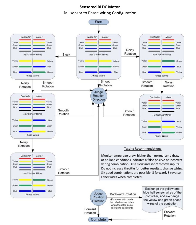
i realized this after having written a little hack to remap phase wires in software on the fly (with uart keypresses), and accidentally spun the wheel in reverse (and it sounded fine-ish)... then i took an another detailed look at the hall sensor states and was like "uhh, that's reverse."

So, effectively i was trying to run the wheel in reverse from what the software was expecting (and no surprise that interpolation doesnt work in that situation).

A little bit of experimenting (and applying a fixed software remap to the hall sensor order - i'm not resoldering the wires going to the connector lol) later and I just did a nice test run (it runs silent and has torque). There's still plenty to do but atleast I have a way better starting point 💚
 
Yeah, that's it. May it be that the firmware has a different layout from the original?

Is there a diagram or text resource I can use to compare and verify pins?
So I've just in case probed the phases and hall sensors of my hub motor but found no abnormalities. Now I've confirmed that there's nothing wrong on the motor side and this is a controller issue.

I've also tested the mosfets on my controller and found no issues.

I'll try to switch phase wires as in this post and see if anything changes.

Edit:
As expected it didn't make a difference. Could it be that the new controllers have a different layout?

Is there anything else I can try? I doubt that there could be any electrical error on the circuit board as I did everything following the wiki and met no problems along the way.

Edit 2:

I've used this resource to verify my pins and traces, pwm high and low, hall sensors and all of the remaining pins line up with their "documented" destination.

I'm lost, does anyone have an idea of how I should continue debugging? Any specific parts of the circuit I should inspect? Or any values I should provide?

Edit 3:

So I don't know what happened, I used a Windows 7 virtual machine with usb passthrough, installed sdcc 4.1.0, java 8 and stvd, compiled the firmware and flashed it through the vm.

Somehow this worked and my motor is now turning!
 
Last edited:
Edit 3:

So I don't know what happened, I used a Windows 7 virtual machine with usb passthrough, installed sdcc 4.1.0, java 8 and stvd, compiled the firmware and flashed it through the vm.

Somehow this worked and my motor is now turning!
Ohhhhh, if you just installed sdcc from your linux distro, it likely (if they're up-to-date) is sdcc 4.2.0, which for some unknown reason (nobody has investigated deeply enough, i assume) miscompiles the firmware. You need 4.1.0 for now.

EDIT: I'm editing to avoid double-posting; effectively jsut another rant-y post:

Why is the firmware listening to PAS while not moving or moving backwards* ?!?; i wired up my PAS and now if you free-kick the pedals around in reverse (with the bike just, you know, parked and leaning on its kickstand next to you) the bike tries to make a hasty escape for an another space and time (the same can happen if you just push the bike backwards, but you need to push quite fast.)

(*Having read the motor code, i think it doesnt really have a "motion in reverse" detector either... *sigh*)
 
(*Having read the motor code, i think it doesnt really have a "motion in reverse" detector either... *sigh*)
Perhaps you should buy glasses :)
The parameter PAS threshold sets the threshold for the reverse detection. The direction information is hidden in the duty cycle of the PAS signal for "normal, cheap" PAS sensors.
Read the wiki carefully!

regards
stancecoke
 
Last edited:
Ohhhhh, if you just installed sdcc from your linux distro, it likely (if they're up-to-date) is sdcc 4.2.0, which for some unknown reason (nobody has investigated deeply enough, i assume) miscompiles the firmware. You need 4.1.0 for now.
No, I deliberately downloaded and compiled the source code for SDCC 4.1.0. I doubt that SDCC was the major problem here, I believe that it might have been stm8-binutils that was the culprit, might also be the "Makefile_linux" that's not being maintained or not being compatible in some way. Casainho used linux to compile this firmware, I don't know which distro he used but I suppose it might have been some version of Ubuntu. I myself use Arch and that might be the problem :ROFLMAO:.
 
Perhaps you should buy glasses :)
Perhaps you should reduce the snark.... maybe me too... but i'll give you this one back:
Have you read about static variables and the post-increment operator since 2017? ;)
(I'm not sure if that disabled chunk of code is any good regardless tbh, another feature to make the control response even slushier is not what we need... oh my gosh the defaults were sooooooo unresponsive (i've gotten mine a lot better))

The actual answer seems to be that i need to check the "PAS inverted" checkbox, even though the PAS sensor is physically on the left side for me - i did an experiment and then some math and the default of 1.9 is a fine value for the threshold on my bike (got about 2.0, but close enough..)

I'm not planning on actually biking with PAS (i prefer no surprise extra assist), but I wired it in because i might write some code that uses the "are we pedalling or not" information.

But your answer didn't address the fundamental part of the rant, which is that this just shouldnt happen, even if misconfigured. (and you can get any duty cycle you want if your pedal motion is funky enough :p, seems like an unreliable indicator...)

No, I deliberately downloaded and compiled the source code for SDCC 4.1.0. I doubt that SDCC was the major problem here, I believe that it might have been stm8-binutils that was the culprit, might also be the "Makefile_linux" that's not being maintained or not being compatible in some way. Casainho used linux to compile this firmware, I don't know which distro he used but I suppose it might have been some version of Ubuntu. I myself use Arch and that might be the problem :ROFLMAO:.
Oh, that is also possible. (But also, the java configurator doesnt really work as-is on linux either, so hmm... how'd you fix that?)
(It fails to run "cmd" and injects "Error" into the throttle low value field which was .... unexpected behaviour.)

I wanted to compile the thing on my ARM linux laptop, so i looked at both makefiles, decided that it's ridiculous that we have two of them (and also, didn't want to compile stm8-binutils because it's obscure and not actually necessary, it seems),
modified Makefile_windows to work on either one (and named it Makefile as it should be), wrote a "configuration appliication" script for linux, modified the java configurator a bit (i've not tested the modified one on windows yet)... i should push atleast these bits onto github tbh.

EDIT:
(it's not complete, i didnt fix the apply option bytes option in the configurator... also apply_config.sh shouldnt use sudo, but instead there should be instructions to put in the udev permissions file for stlink, but hey i was moving fast lol)
 
Last edited:
Oh, that is also possible. (But also, the java configurator doesnt really work as-is on linux either, so hmm... how'd you fix that?)
(It fails to run "cmd" and injects "Error" into the throttle low value field which was .... unexpected behaviour.)
Yeah, that's an issue I've encountered, nevertheless it still writes to the config.h and therefore I just used it as an easy way to set the config file. Will definitely check out your fixes when I get my motor wired up)
 
which is that this just shouldnt happen, even if misconfigured. (and you can get any duty cycle you want if your pedal motion is funky enough :p, seems like an unreliable indicator...)
I agree 1000%! Using a dual hall PAS with quadrature signal would be much easier to handle and much more reliable. But users seem to prefer cheap, cheap, cheap.

PAS_Signal_Levels.jpg

Source:

regards
stancecoke
 
Last edited:
Hi all,
gentlemen, please help with advice
I am redoing himo c20 with DD. first of all, I threw out a poor proprietary controller and installed kt36 / 48svprd-fff1-l
it was only possible to start it after swapping 2 phases and 2 halls.
it worked great, but the recuperation did not work, it twitched and made noise.
After installing the free firmware, for a long time I could not start it at all until I swapped back phases and halls.
I found up the motor angle and at idle it rotate and does not buzz, the current seems to be normal, power is ~20W
BUT under load it produce a very low torque and trembles, such small shocks are clearly felt. if you accelerate with the pedals, it seems to work better at speed;
the controller has a phase current sensor, options I use only "rotor angle correction" and "regen digital"
if I enable "disable interpolation" option, it only makes noise and twitches, it was not possible to start motor at all
suggest me where to dig)
thanks

UP
there is another issue with regeneration: I see a current pulse about 5A when the brake lever is pressed, which then gradually decreases, and the same sharp current pulse when released. I didn’t tighten the cable on purpose so that the digital signal would arrive before the brake pads worked. if you press and release often - these peaks always repeat
UP2
also if I start pedaling from 0 speed, I see a negative regeneration current and this significantly hamper acceleration on pedals. tried to use PWM_AUTO_OFF - but it completely kills the regeneration, I can fix this function (I have a lot of experience in programming), but I'm wondering why the regeneration works from 0 speed on the pedals
 
Last edited:
No, I deliberately downloaded and compiled the source code for SDCC 4.1.0. I doubt that SDCC was the major problem here, I believe that it might have been stm8-binutils that was the culprit, might also be the "Makefile_linux" that's not being maintained or not being compatible in some way. Casainho used linux to compile this firmware, I don't know which distro he used but I suppose it might have been some version of Ubuntu. I myself use Arch and that might be the problem :ROFLMAO:.
I am using Debian based Linux with sdcc 4.3 - it works. I just got binutils from platformio project.
your problem was probably in option bytes - a timer is configured there, and in linux there is no beautiful gui for this)))
 
Last edited:
FYI: currently "power based control" is frocked up:

It does not take into account that uint32_current_target has the cal_b offset added to it already.
Example: cal_b of 300, a 36V nominal system, 10 Amps (simple numbers :p), at 42V (full battery),
should be 36V*10A = 360W -> 360W/42V = 8.57A. Lets try the math the code uses.
target 300+100 = 400,
42V * 256/69 = max battery 155.82 (lets say we wrote 156 in the config, but it's 155 when we run...)
30V * 256/69 = min battery 111.30 ... say 111
Nominal voltage is then "133" (36Vish)
target 400 * 133 nom voltage value / 155 real voltage value => target 343 = 4.3 Amps = about 181W 😟
Alternatively, at empty battery, 400 * 133 / 111 = 479 = 17.9 Amps => 537W 😬
This part not hard to fix, but yeah... oh my, good that i noticed before enabling it.

I think it should also respect the maximum battery current value at lower voltages, ergo the
configuration parameter used for determining max power should not be maximum battery current,
but there should be a seperate maximum power parameter.
 
It does not take into account that uint32_current_target has the cal_b offset added to it already.
you are right, this is a bug in the master branch.
In the branch that I use(d), it's correct, the offset is added afterwards ;)


regards
stancecoke
 
you are right, this is a bug in the master branch.
In the branch that I use(d), it's correct, the offset is added afterwards ;)


regards
stancecoke
… speaking of power based control: I am using the torque from x4 branch w/ BlueOsec App: Eveything works fine, but when I enable power based control, the system does not turn the motor at all (I am using throttle only)
Is rhis also a known bug, or am I doing something wrong?
 
can anyone help me with my setup?
my motor spins at angle setting from 193 to 215. and I don't like how it works at all.
if interpolation is disabled, then it only makes noise and jerks;
maybe this is evidence that phases are connected incorrectly? everyone here has an angle a little different from 255, as I see it.

UP: swapped phases, but it did not help. I had to change the angle from 193 to 25. just shifted 60 degrees, but it twitches and trembles as before. both during acceleration and during regeneration. feels like small jolts, it's unpleasant to ride
any help is highly appreciated
 
Last edited:
Back
Top