Tkank you,
I wrote a code that allows to remap pins without physically soldering wires and I tried all 36 combinations, found a few more that the wheel spins on, and only one that works with an angle 20.
I'm curious about how you went about remapping the output phases (mine rotated motor angle by -120, 0 or 120 degrees (-85,0,85 units) and optionally swapped phases A and C in the PWM output.)
(EDIT: It's notable that phase B has the current sensor, and you cant move the sensor around, so ... mind that, i just adjusted the wires physically correct before moving on with the finetuning with the current sensor, below.)
Anyways, First I'd double-check that the hall state order when spinning forwards is correct (motor.c +ACAcommons.c records that in uint8_t_hall_order[]) (462315 or a rotation thereof, but 6 after 4 etc)
After this you'd only have the 6 permutations of phase wires to check btw, sorry that you went through all 36 :|
Then I'd check that you have proper phase B current sensor readings (do not enable "Enable rotor angle correction" + interpolation before that... you can have interpolation without the current sensor, just not the rotor angle correction) - those are recorded in uint8_t_hall_case[] by motor.c, just make sure it kinda sinewaves around 128 while operating.
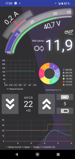
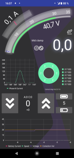
If the phase B current sensor works, you can use that to finetune the motor specific angle (i made it possible to adjust it by one unit either way via uart, that was handly) - see where ui8_position_correction_value goes while running with interpolation and rotor angle correction, and adjust motor angle so it the correction value stays near 127. For my DYU D3F the motor specific angle (in the units used by the configurator) seems to be about 200, which i was surprised about (237 was functional but so far forwards that it had trouble getting started and ui8_position_correction_value just clamped down to 111 to try to fix it.)
After this, you can check the uint8_t_60deg_pwm_cycles[] recorded by motor.c to check how much time is spent in each hall state. Mine were withing an unit or two of eachother so i was like that seems good enough, but basically in theory if your hall sensors have unequal spacing that's where it would show, and you could adjust the hall state angles accordingly.
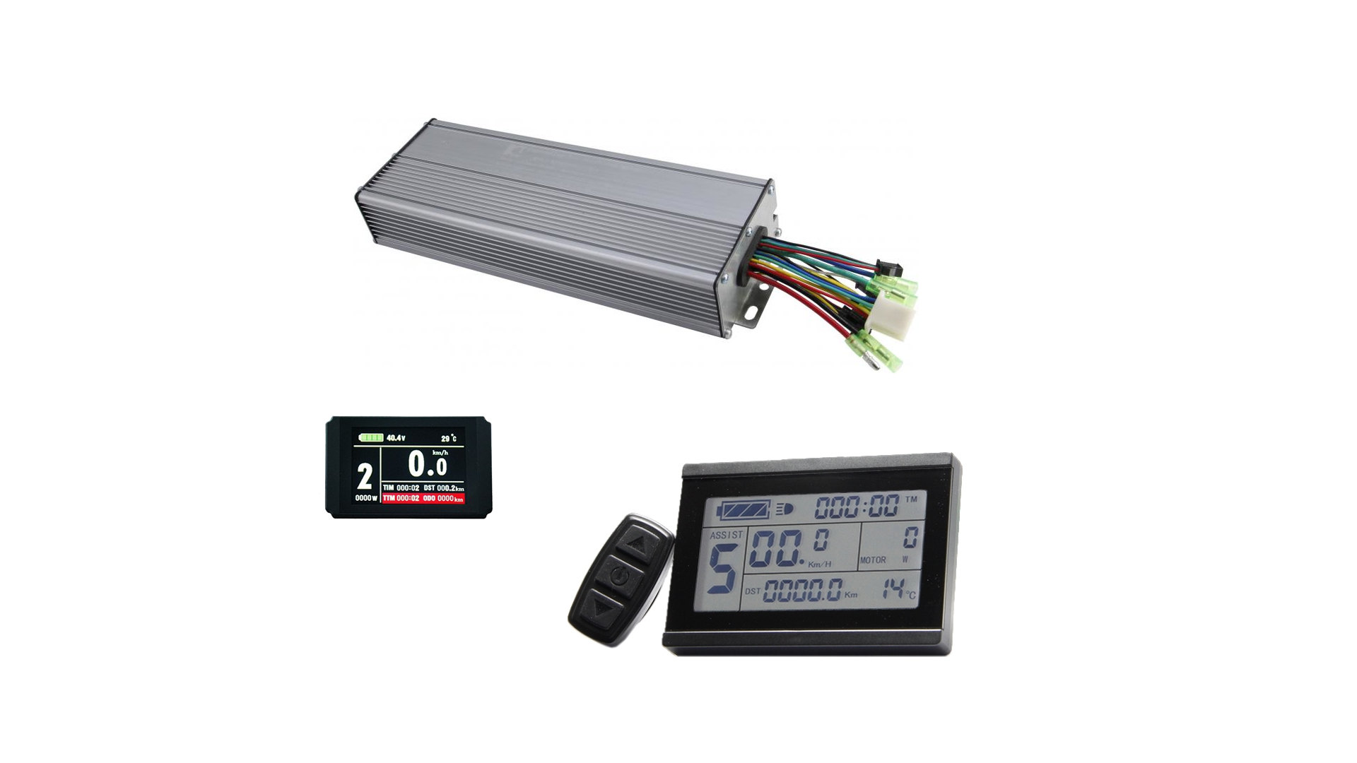
EDIT: Unrelated recommendation, after it otherwise works: do actually check how much current your controller pulls vs. what you thought you configured it for. For my KT24/36 it seems to be about 1.5x of what you'd expect from the raw value - that is, a cal_a of about 67, but cal_a is used only for display purposes (literally, in display.c etc), you still need to account for it in the battery, phase and regen current variables. The wiki does tell you this how it is, but it's just... i wasn't expecting that big of a discrepancy.
(Sidenote: this configurator is way too coder-oriented to be a proper end-user tool, nobody wants to configure times in units of 64 microseconds, angles in units of 360/256 degrees, currents in raw ADC readouts, etc.)

")