
You are using an out of date browser. It may not display this or other websites correctly.
You should upgrade or use an alternative browser.
You should upgrade or use an alternative browser.
KT motor controllers -- Flexible OpenSource firmware for BMSBattery S/Kunteng KT motor controllers (0.25kW up to 5kW)
- Thread starter casainho
- Start date
Almosty all “factory” firmware (including KT original fw) uses “speed (rpm) control”, and not “torque (current) control” for the throttle. That is, by shifting the knob on 2-3 mm, the motor (unloaded wheel) turns will be 5-10 rpm, moving another 1 mm - 30-50 rpm, etc.j bjork said:A question, how is the trottle response compeared to the standard fw? I think it is a bit slow on the kt fw.
This behavior allows you to stably maintain the desired speed, especially at low speeds (5-8 km / h), the current speed depends little on small changes in the terrain, it is stable.
And yes, this mode feels like a "quick response" knob.
Unfortunately, this firmware uses a "dumb" throttle control method - "Torgue (current)". An unloaded wheel immediately starts at full speed, driving at low speeds is difficult and unstable, the throttle response is perceived as "viscous", and the acceleration speed and speed change is unpredictable even with slight inclines/rises of 0.5-1 degrees.
Unfortunately, this is the only reason why I cannot use this excellent firmware.
j bjork
1 MW
Thanks, that sounds interesting ")
Maby I should try to flash my controller this weekend..
It would be interesting to hear the developers comments on this.
Maby I should try to flash my controller this weekend..
It would be interesting to hear the developers comments on this.
stancecoke
1 MW
I can't follow kkm's arguments, he reported his experience before:j bjork said:It would be interesting to hear the developers comments on this.
I never heard about this disappointing behaviour from other users...kkm said:Flexible OpenSource firmware works excellently on all my geared motors - Bafang SWX02, MXUS XF15R and XF08. Very quiet, there are no unpleasant vibrations and some resonances on the ebike frame (as it was on the stock firmware).
But ... Thumb throttle control... Very accurate and predictable work on the original firmware (and other Chinese controllers), the acceleration is predictable, the response of the thumb throttle is accurate, and it is easy to maintain the selected speed.
Now... I practically cannot use the throttle knob - poorly predicted work, it is difficult to control the chosen speed, "viscous" acceleration.
I don't know if he set the proper voltage range for his throttle,
Perhaps some other users can give a statement, as I'm not using a throttle but a bottom bracket torquesensor.... :wink:
regards
stancecoke
j bjork
1 MW
So it should still be speed throttle, not torque?
I've got a KT60SVPRKD controller with a low voltage protection of 50V. I want to use that controller with my 48V battery but unfortunately it will shut down as soon as I hit the throttle because of the LVC. I saw that you can modify the LVC, so would that fix my problem or is it a hardware problem?
stancecoke
1 MW
j bjork said:So it should still be speed throttle, not torque?
The throttle controls the current (= torque), that's the "normal" behaviour of every throttle in any motorcycle or car.
Xnyle has build in the option assist lvl affects throttle, with this you can reduce the max amps of full throttle for low speeds. (I never tried it, as written before)
No hardware problem, you can define any LVC with our open firmware. But I don't know, if your LCD works with lower voltages, as a special "high voltage" version of the LCD3 exists.Marv1337n said:I saw that you can modify the LVC, so would that fix my problem or is it a hardware problem?
regards
stancecoke
stancecoke said:j bjork said:So it should still be speed throttle, not torque?
The throttle controls the current (= torque), that's the "normal" behaviour of every throttle in any motorcycle or car.
Xnyle has build in the option assist lvl affects throttle, with this you can reduce the max amps of full throttle for low speeds. (I never tried it, as written before)
No hardware problem, you can define any LVC with our open firmware. But I don't know, if your LCD works with lower voltages, as a special "high voltage" version of the LCD3 exists.Marv1337n said:I saw that you can modify the LVC, so would that fix my problem or is it a hardware problem?
regards
stancecoke
Yeah I've got the 60V/72V LCD3 display but it works with my 48V battery, the only thing is that it's pretty dim.
This is just meant to be a temporary solution until my 66V LiPo build is finished.
casainho
10 GW
- Joined
- Feb 14, 2011
- Messages
- 6,058
If I remember correctly, I implemented control of both motor current and wheel speed. The controller on firnware would be limited for the first variable to hit the max value, be it wheel speed or current. Throttle position did setup a target wheel speed and current, where half of throttle position was equal to half of max current and half of max speed (the one defined on LCD).
stancecoke said:j bjork said:So it should still be speed throttle, not torque?
The throttle controls the current (= torque), that's the "normal" behaviour of every throttle in any motorcycle or car.
Xnyle has build in the option assist lvl affects throttle, with this you can reduce the max amps of full throttle for low speeds. (I never tried it, as written before)
No hardware problem, you can define any LVC with our open firmware. But I don't know, if your LCD works with lower voltages, as a special "high voltage" version of the LCD3 exists.Marv1337n said:I saw that you can modify the LVC, so would that fix my problem or is it a hardware problem?
regards
stancecoke
j bjork
1 MW
stancecoke said:j bjork said:So it should still be speed throttle, not torque?
The throttle controls the current (= torque), that's the "normal" behaviour of every throttle in any motorcycle or car.
Xnyle has build in the option assist lvl affects throttle, with this you can reduce the max amps of full throttle for low speeds. (I never tried it, as written before)
Sounds good, I don´t think I will need the limit. But it would be interesting to try torque throttle, and see if it will be more responsive.
For my bike am I using a kt36/48ZWS, but for my mopet/scooter I would like to use KT60 controller to get at least 2KW.
After flashing the software on the KT60SVP and powering it on with a testing voltage of 36V I blew some mosfets.
After removing all of them and retrying it with only the low side active (3 mosfets) It didn't blew. but adding a high side mosfet created a big spark.
comparing the KT36/48 to the KT60 pcb i concluded that the pin-out of the microchip is the same but the mosfet-driver-circuit is different. Only the low side is the same (sort of). The high side consist of a PNP trasistor (Y2) in the KT36/48 and a NPN transitor (Y1) in the KT60.
My question: How can I invert the duty cycle of the HIGH side. So if I want a duty cycle of 200 the chip need to been set to 55, and from 0 to 255, and from 255 to 0 etc. I am a starter in programming, only familiar with Arduino
The marking on the transistor is G1(NPN) Y1(NPN) Y2(PNP).
simple diagram in the pictures
HIGH SIDE KT36/48ZWSRM-SLS02G
View attachment 6
LOW SIDE KT36/48ZWSRM-SLS02G

high side right, low side left KT36/48ZWSRM-SLS02G

HIGH SIDE KT60SVPRCKD-JLS01

LOW SIDE KT60SVPRCKD-JLS01

HIGH SIDE left, Low side right KT60SVPRCKD-JLS01

KT60SVPRCKD-JLS01 & KT36/48ZWSRM-SLS02G

After flashing the software on the KT60SVP and powering it on with a testing voltage of 36V I blew some mosfets.
After removing all of them and retrying it with only the low side active (3 mosfets) It didn't blew. but adding a high side mosfet created a big spark.
comparing the KT36/48 to the KT60 pcb i concluded that the pin-out of the microchip is the same but the mosfet-driver-circuit is different. Only the low side is the same (sort of). The high side consist of a PNP trasistor (Y2) in the KT36/48 and a NPN transitor (Y1) in the KT60.
My question: How can I invert the duty cycle of the HIGH side. So if I want a duty cycle of 200 the chip need to been set to 55, and from 0 to 255, and from 255 to 0 etc. I am a starter in programming, only familiar with Arduino
The marking on the transistor is G1(NPN) Y1(NPN) Y2(PNP).
simple diagram in the pictures
HIGH SIDE KT36/48ZWSRM-SLS02G
View attachment 6
LOW SIDE KT36/48ZWSRM-SLS02G
high side right, low side left KT36/48ZWSRM-SLS02G
HIGH SIDE KT60SVPRCKD-JLS01
LOW SIDE KT60SVPRCKD-JLS01
HIGH SIDE left, Low side right KT60SVPRCKD-JLS01
KT60SVPRCKD-JLS01 & KT36/48ZWSRM-SLS02G
casainho
10 GW
- Joined
- Feb 14, 2011
- Messages
- 6,058
Nice findings!!
Here, in pwm.c file, the TIM1_OCPOLARITY_HIGH,
TIM1_OCNPOLARITY_LOW,.
There is configured polarity for OC and OCN channels. Please adjust for all 3 pwm channels.
Also first disable the PWM as seen on that piece of code, by setup TIM1_OUTPUTSTATE_ENABLE,
TIM1_OUTPUTNSTATE_ENABLE and test before enable on all of the channels, to make sure the change you did do work.
I hope stacecoke can also validate this my suggestion.
void pwm_init_bipolar_4q (void)
{
TIM1_TimeBaseInit(0, // TIM1_Prescaler = 0
TIM1_COUNTERMODE_CENTERALIGNED1,
(512 - 1), // clock = 16MHz; counter period = 1024; PWM freq = 16MHz / 1024 = 15.625kHz;
//(BUT PWM center aligned mode needs twice the frequency)
1); // will fire the TIM1_IT_UPDATE at every PWM period cycle
//#define DISABLE_PWM_CHANNELS_1_3
TIM1_OC1Init(TIM1_OCMODE_PWM1,
#ifdef DISABLE_PWM_CHANNELS_1_3
TIM1_OUTPUTSTATE_DISABLE,
TIM1_OUTPUTNSTATE_DISABLE,
#else
TIM1_OUTPUTSTATE_ENABLE,
TIM1_OUTPUTNSTATE_ENABLE,
#endif
255, // initial duty_cycle value
TIM1_OCPOLARITY_HIGH,
TIM1_OCNPOLARITY_LOW,
TIM1_OCIDLESTATE_RESET,
TIM1_OCNIDLESTATE_SET);
eimertvm said:For my bike am I using a kt36/48ZWS, but for my mopet/scooter I would like to use KT60 controller to get at least 2KW.
After flashing the software on the KT60SVP and powering it on with a testing voltage of 36V I blew some mosfets.
After removing all of them and retrying it with only the low side active (3 mosfets) It didn't blew. but adding a high side mosfet created a big spark.
comparing the KT36/48 to the KT60 pcb i concluded that the pin-out of the microchip is the same but the mosfet-driver-circuit is different. Only the low side is the same (sort of). The high side consist of a PNP trasistor (Y2) in the KT36/48 and a NPN transitor (Y1) in the KT60.
My question: How can I invert the duty cycle of the HIGH side. So if I want a duty cycle of 200 the chip need to been set to 55, and from 0 to 255, and from 255 to 0 etc. I am a starter in programming, only familiar with Arduino
The marking on the transistor is G1(NPN) Y1(NPN) Y2(PNP).
simple diagram in the pictures
HIGH SIDE KT36/48ZWSRM-SLS02G
KT36 48 HIGH SIDE.jpg
LOW SIDE KT36/48ZWSRM-SLS02G
KT36 48 LOW SIDE.jpg
high side right, low side left KT36/48ZWSRM-SLS02G
KT36 48, righ HIGH, left LOW.jpg
HIGH SIDE KT60SVPRCKD-JLS01
KT60 HIGH SIDE.jpg
LOW SIDE KT60SVPRCKD-JLS01
KT60 LOW SIDE.jpg
HIGH SIDE left, Low side right KT60SVPRCKD-JLS01
KT60 righ LOW, left HIGH.jpg
KT60SVPRCKD-JLS01 & KT36/48ZWSRM-SLS02G
KT60 up, KT36 48 down.jpg
Thank you for the help.
For the past few days I have been busy with troubleshooting the KT60SVP...
I found out that not only the low side phase is flipped, but also its mosfet driver is broken.
So I ordered replacement parts.
I will come back here to write if the suggestion worked.
For the past few days I have been busy with troubleshooting the KT60SVP...
I found out that not only the low side phase is flipped, but also its mosfet driver is broken.
So I ordered replacement parts.
I will come back here to write if the suggestion worked.
casainho said:Nice findings!!
Here, in pwm.c file, the TIM1_OCPOLARITY_HIGH,
TIM1_OCNPOLARITY_LOW,.
There is configured polarity for OC and OCN channels. Please adjust for all 3 pwm channels.
Also first disable the PWM as seen on that piece of code, by setup TIM1_OUTPUTSTATE_ENABLE,
TIM1_OUTPUTNSTATE_ENABLE and test before enable on all of the channels, to make sure the change you did do work.
I hope stacecoke can also validate this my suggestion.
void pwm_init_bipolar_4q (void)
{
TIM1_TimeBaseInit(0, // TIM1_Prescaler = 0
TIM1_COUNTERMODE_CENTERALIGNED1,
(512 - 1), // clock = 16MHz; counter period = 1024; PWM freq = 16MHz / 1024 = 15.625kHz;
//(BUT PWM center aligned mode needs twice the frequency)
1); // will fire the TIM1_IT_UPDATE at every PWM period cycle
//#define DISABLE_PWM_CHANNELS_1_3
TIM1_OC1Init(TIM1_OCMODE_PWM1,
#ifdef DISABLE_PWM_CHANNELS_1_3
TIM1_OUTPUTSTATE_DISABLE,
TIM1_OUTPUTNSTATE_DISABLE,
#else
TIM1_OUTPUTSTATE_ENABLE,
TIM1_OUTPUTNSTATE_ENABLE,
#endif
255, // initial duty_cycle value
TIM1_OCPOLARITY_HIGH,
TIM1_OCNPOLARITY_LOW,
TIM1_OCIDLESTATE_RESET,
TIM1_OCNIDLESTATE_SET);
eimertvm said:For my bike am I using a kt36/48ZWS, but for my mopet/scooter I would like to use KT60 controller to get at least 2KW.
After flashing the software on the KT60SVP and powering it on with a testing voltage of 36V I blew some mosfets.
After removing all of them and retrying it with only the low side active (3 mosfets) It didn't blew. but adding a high side mosfet created a big spark.
comparing the KT36/48 to the KT60 pcb i concluded that the pin-out of the microchip is the same but the mosfet-driver-circuit is different. Only the low side is the same (sort of). The high side consist of a PNP trasistor (Y2) in the KT36/48 and a NPN transitor (Y1) in the KT60.
My question: How can I invert the duty cycle of the HIGH side. So if I want a duty cycle of 200 the chip need to been set to 55, and from 0 to 255, and from 255 to 0 etc. I am a starter in programming, only familiar with Arduino
The marking on the transistor is G1(NPN) Y1(NPN) Y2(PNP).
simple diagram in the pictures
HIGH SIDE KT36/48ZWSRM-SLS02G
KT36 48 HIGH SIDE.jpg
LOW SIDE KT36/48ZWSRM-SLS02G
KT36 48 LOW SIDE.jpg
high side right, low side left KT36/48ZWSRM-SLS02G
KT36 48, righ HIGH, left LOW.jpg
HIGH SIDE KT60SVPRCKD-JLS01
KT60 HIGH SIDE.jpg
LOW SIDE KT60SVPRCKD-JLS01
KT60 LOW SIDE.jpg
HIGH SIDE left, Low side right KT60SVPRCKD-JLS01
KT60 righ LOW, left HIGH.jpg
KT60SVPRCKD-JLS01 & KT36/48ZWSRM-SLS02G
KT60 up, KT36 48 down.jpg
j bjork
1 MW
Is this a problem only on the kt60? Not kt36/48 18fet?
I remember something about another user earlier in the thread who were modifing an 18fet controller with other mosfets, wires etc. to handle more power. But I think he did not get it running. I think it blew the fuse as soon as he gave throttle or something like that. Sounds like it could have been the same problem..
I remember something about another user earlier in the thread who were modifing an 18fet controller with other mosfets, wires etc. to handle more power. But I think he did not get it running. I think it blew the fuse as soon as he gave throttle or something like that. Sounds like it could have been the same problem..
j bjork
1 MW
I programmed my controller today, but there are some problems.
Before I changed fw I mesured consumption, it used about 1,5A at full speed with the wheel in the air. It was working fine.
After programming with the wheel in the air I can not get a steady rotation. I get power for maby half a second, then the wheel rotates freely for maby 2 seconds. Then power for maby half a second again.
On the ground it is noisy and draws many amps. I don´t have a bluetooth module yet, so I cant use the app. But I tried the diagnosis on the computor, but I can´t make much sense of it. I get some numbers, but not any foult messages or something like that.
Here are the settings, if you can see something compleatly wrong:
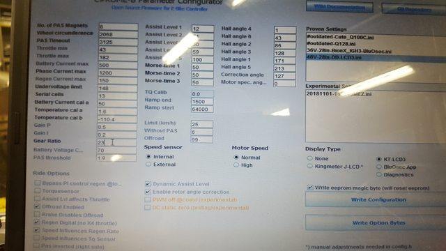
I have an 18fet controller and a DD hub. I think it is a copy of a 9C 2706
Before I changed fw I mesured consumption, it used about 1,5A at full speed with the wheel in the air. It was working fine.
After programming with the wheel in the air I can not get a steady rotation. I get power for maby half a second, then the wheel rotates freely for maby 2 seconds. Then power for maby half a second again.
On the ground it is noisy and draws many amps. I don´t have a bluetooth module yet, so I cant use the app. But I tried the diagnosis on the computor, but I can´t make much sense of it. I get some numbers, but not any foult messages or something like that.
Here are the settings, if you can see something compleatly wrong:
I have an 18fet controller and a DD hub. I think it is a copy of a 9C 2706
j bjork
1 MW
Rasing the correction angle seems to help, I changed from 127 to 168 then to 172. It has improved a lot. And setting all speed limits to 99, now i can get stable acceleration. But a bit sluggish.
But the only ting working on the lcd3 is battery voltage, no speed, no symbols for braking, no battery indicator.
It also seems like changing assist level has no effect. I havent tested on the road, but it works on assist 0 with the wheel in the air.
And it has a delay when I release the trottle before it stops pulling.
j bjork
1 MW
This should mean that the halls are in the right order I think?
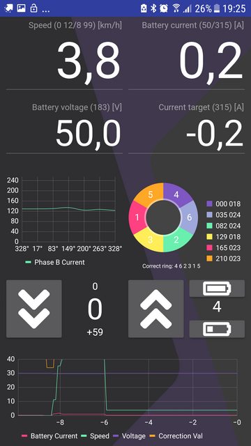
Here I have some correction angle, I think I should get that down to 0?
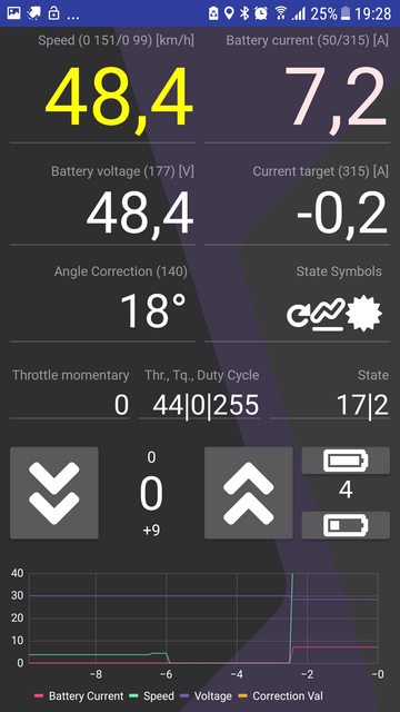
I have tried to adjust the Motor specific angle and the correction at angle, but it dos´nt seem to help much. I don´t find much information about them in the instructions at C#ROME-B
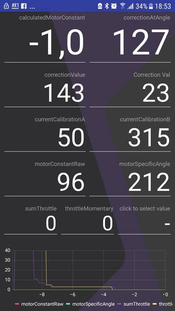
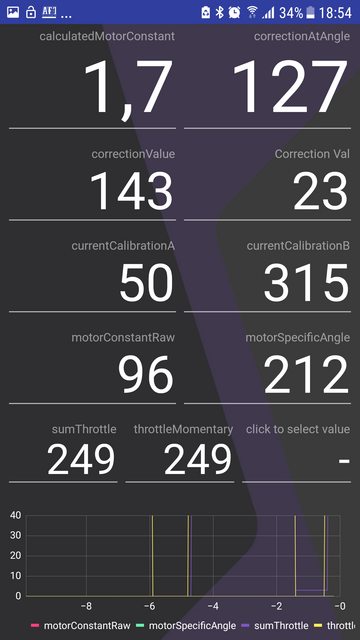
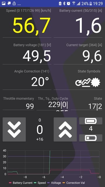
Here are some more values, and does these throttle values mean that I should adjust the min throttle to almost 0 and the max to almost 249?
But the throttle is not very important now, I can probably figure that out later. The main question is how do I get the motor to run smooth?
Here I have some correction angle, I think I should get that down to 0?
I have tried to adjust the Motor specific angle and the correction at angle, but it dos´nt seem to help much. I don´t find much information about them in the instructions at C#ROME-B
Here are some more values, and does these throttle values mean that I should adjust the min throttle to almost 0 and the max to almost 249?
But the throttle is not very important now, I can probably figure that out later. The main question is how do I get the motor to run smooth?
stancecoke
1 MW
keep the correction (at) angle at 127. Play around with the motor specific angle. Sorry the function of correction (at) angle is not dokumented in the wiki yet.
regards
stancecoke
regards
stancecoke
j bjork
1 MW
Thanks. I will try to play around with that some more, but so far not much luck. In the 170:s the wheel is stuck. I beleve I ended up in the 230:s, then I had very low correction angle.
But the bike behaves rather strange. If I pull the throttle it can take off ok, but then start to cogg badly. Sometimes there is no reaction to throttle, on maby the third try it reacts. But then it does not react to the release of trottle ither, I have to keep it still with the brakes for a few seconds.
But the bike behaves rather strange. If I pull the throttle it can take off ok, but then start to cogg badly. Sometimes there is no reaction to throttle, on maby the third try it reacts. But then it does not react to the release of trottle ither, I have to keep it still with the brakes for a few seconds.
stancecoke
1 MW
Hmm, very strange. But I can't help from the distance.
regards
stancecoke
regards
stancecoke
stancecoke
1 MW
Marv1337n said:Does the standard KT controllers come with a higher Phase Amps than Battery Amps?
This is not Kunteng specific, but normal behaviour of any controller, that uses pulse width modulation for driving the motor.
Code:
Iphase = Ibattery/duty cycleregards
stancecoke
casainho
10 GW
- Joined
- Feb 14, 2011
- Messages
- 6,058
I think you mean a limiter for both type of currents. Yes, Kunteng hardware permits that limit and my code does that, even because I think we should limit motor/phase current to protect the controller. I think Stancecoke code does not implement this limit.Marv1337n said:POST A REPLY
Post icon:
None
Subject:
Re: KT motor controllers -- Flexible OpenSource firmware for BMSBattery S/Kunteng KT motor controllers (0.25kW up to 5kW
| |
Smilies
:thumb:


Figured I ask here because I guess the developers of this firmware knows this best.
Does the standard KT controllers come with a higher Phase Amps than Battery Amps? e.g. 45A from the Battery but 70A goes to the motor?
Here is the configuration on config.h file:
Code:
// *************************************************************************** //
// MOTOR CONTROLLER

// Choose your controller max current and max regen current
//
// S06S controller holds 15 amps as max current
#define ADC_MOTOR_CURRENT_MAX		43 // each unit = 0.35A; 43 = 15A (tested on S06S motor controller)
#define ADC_MOTOR_REGEN_CURRENT_MAX	28 // CAN'T be more than 66 units!! each unit = 0.35A; 20 = 10A but the brake/regen must be only for a few seconds!!

// *************************************************************************** //
// BATTERY

#define ADC_BATTERY_CURRENT_MAX		42 // each unit = 0.35A | in this example, 42 * 0.35 ~= 15 amps
#define ADC_BATTERY_REGEN_CURRENT_MAX	5 // CAN'T be more than 66 units!! each unit = 0.35A
Here is the piece of code that implements that:
Code:
/****************************************************************************/
  // PWM duty_cycle controller:
  // - limit battery overvoltage
  // - limit battery undervoltage
  // - limit battery max current
  // - limit battery max regen current
  // - limit motor max current
  // - limit motor max regen current
  // - limit motor max ERPS
  // - ramp up/down PWM duty_cycle value

  if ((UI8_ADC_BATTERY_CURRENT > ui8_adc_target_battery_current_max) || // battery max current, reduce duty_cycle
      (ui8_adc_motor_current > ui8_adc_target_motor_current_max) || // motor max current, reduce duty_cycle
      (ui16_motor_speed_erps > MOTOR_OVER_SPEED_ERPS) || // motor speed over max ERPS, reduce duty_cycle
      (UI8_ADC_BATTERY_VOLTAGE < ((uint8_t) ADC_BATTERY_VOLTAGE_MIN))) // battery voltage under min voltage, reduce duty_cycle
  {
    if (ui8_duty_cycle > 0)
    {
      ui8_duty_cycle--;
    }
}stancecoke
1 MW
casainho said:I think Stancecoke code does not implement this limit.
Sorry, you are not up to date, the phase current limitation is implemented since several month
regards
stancecoke
casainho
10 GW
- Joined
- Feb 14, 2011
- Messages
- 6,058
Sorry, I remember now. I remember that you did implement like I did on TSDZ2 firmware.stancecoke said:casainho said:I think Stancecoke code does not implement this limit.
Sorry, you are not up to date, the phase current limitation is implemented since several month
regards
stancecoke
Similar threads
- Replies
- 129
- Views
- 46,314
- Replies
- 2
- Views
- 3,587