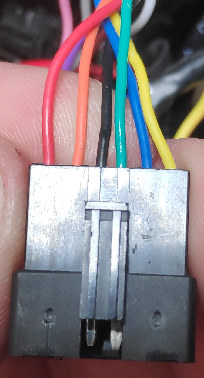
As E-HP said, that display unit is unlikely to work with your controller.
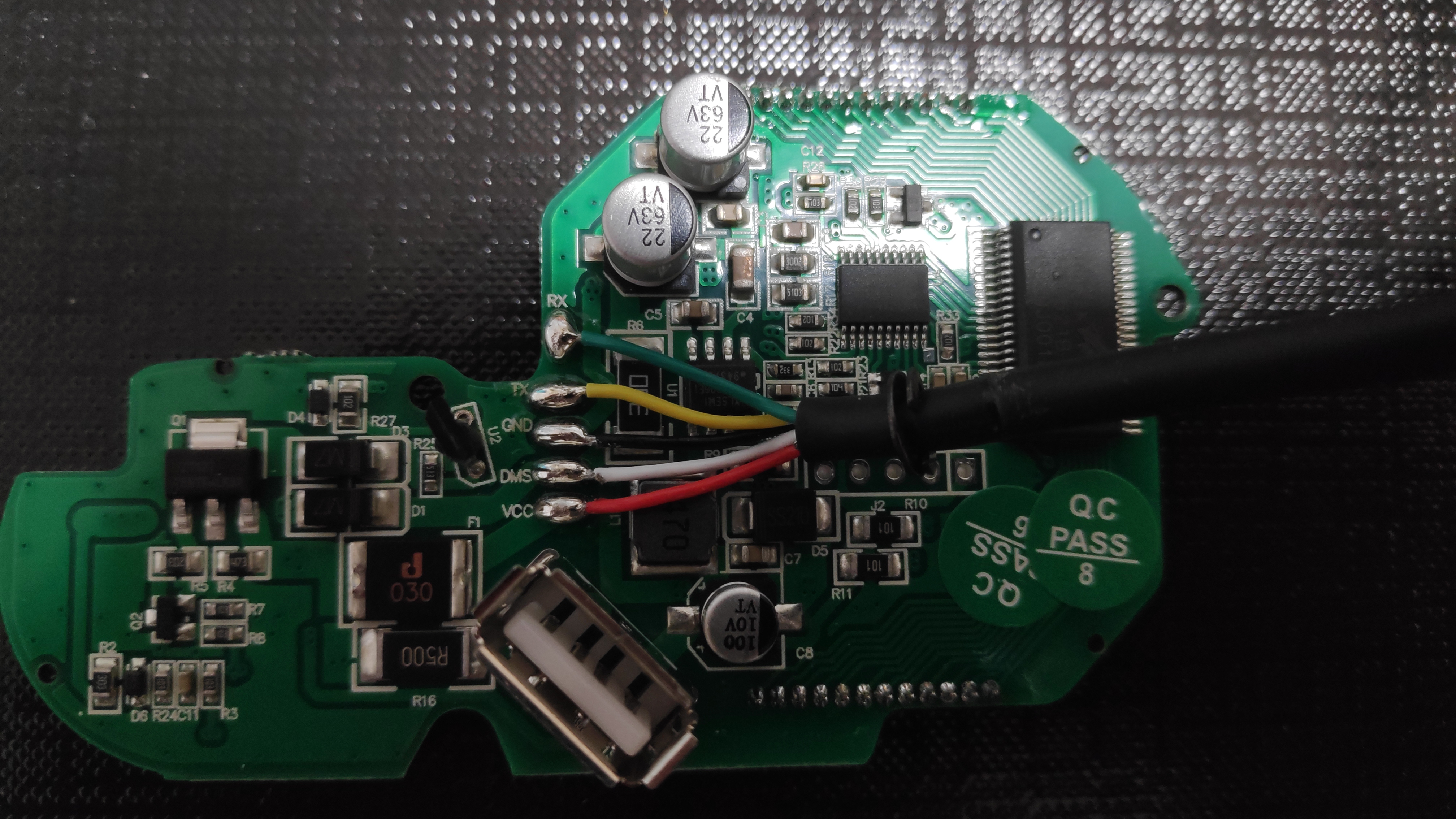
I think I see the hall sensor itself, sticking up out of the board at "U2"; a black unit with three silver leads going straight down into the board.
If you don't need any of the other functions of that unit other than the throttle, you could solder 5v, ground, and signal wires from the controller's throttle connector (probably number 9, translated as "change") to the pads the sensor is attached to on the board, and just use the sensor itself.
If VCC on this display is like many displays and uses battery voltage (can't tell from the available information), then you could wire battery positive + to the VCC wire, battery ground (-) to the GND wire, and then the display will itself power the throttle sensor. Then you can just solder a wire to the signal pad of the throttle sensor (probably the pad closest to the letters DMS) from the controller's throttle signal wire (and leave the controller's 5v and ground throttle cable wires not connected). In this case the display will be powered but it will not be able to talk to the controller--only the throttle itself will work, not any of it's other functions.
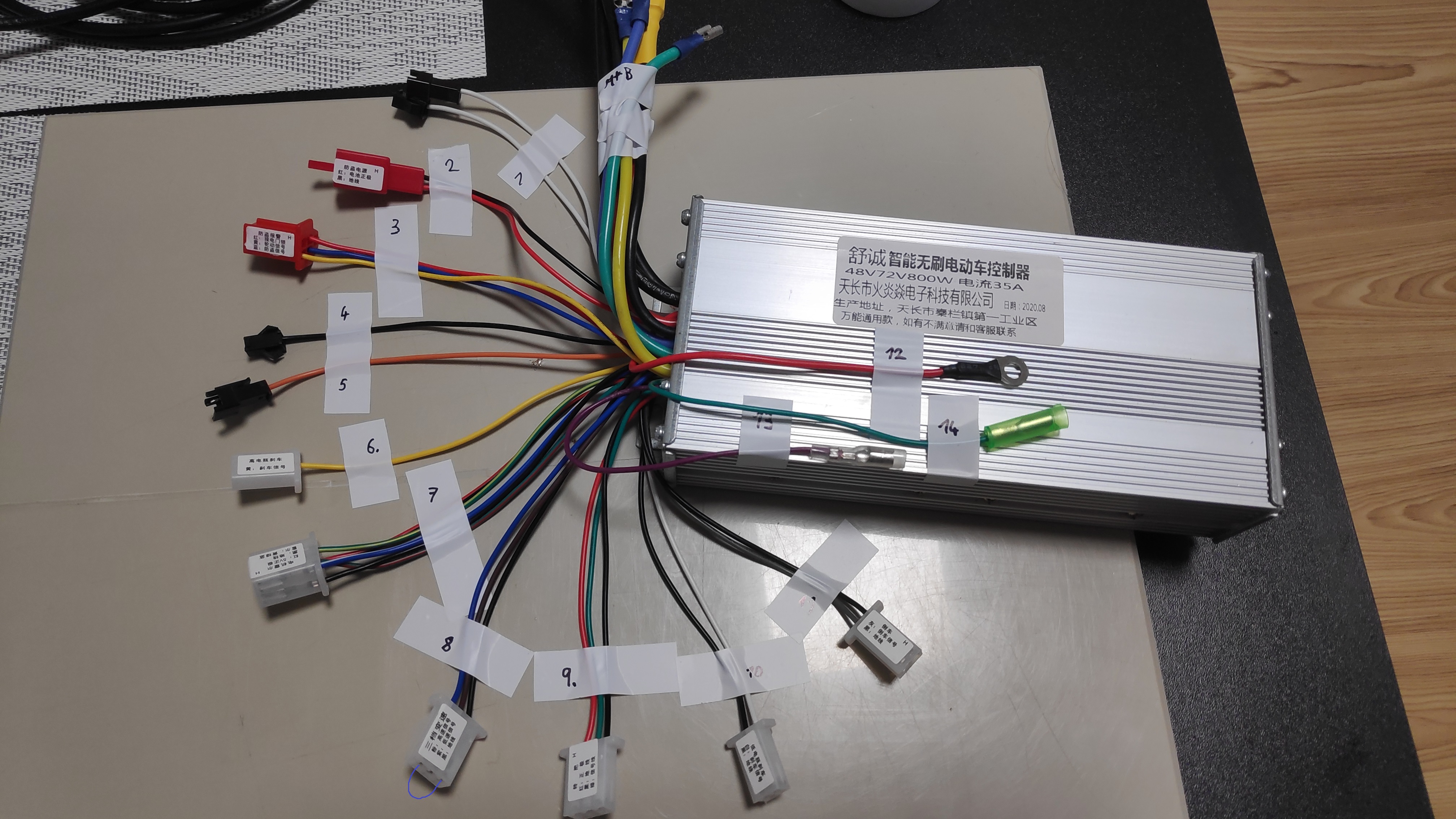
Regarding the controller wires:
1 is what you use to tell the controller how to spin the motor correctly. Usually, once everything is all wired up and ready to go, you make sure battery power is off. Plug the two ends of 1 into each ohter, then turn on the battery power. Wait a moment and the wheel will spin; if it spins in the right direction, turn off batteyr and unplug the 1 connectors from each other. Now when you turn it on each time it knows how to drive the motor. If it spins the wrong direction, just repeat the steps a second time.
2 and 3 you won't use unless you have a compatible alarm system (if you don't know, then you don't have one). Just leave them not connected.
6 is used if you have a taillight on a scooter that is turned on by 12v or more, and activated by your brake lever. If so, you connect this to the light's switched wire, and then it will engage whatever braking this controller has (or just turn off the motor) whenever you brake. If you don't have a light like this then don't use the connector. Same if you don't want an ebrake function.
7 connects to the motor's hall sensor wires, as noted in the translation. Since it has self-learn on wire pair 1, you can just color match your hall wires; it doesn't really matter except for 5v and ground.
8 If you have a three speed swtich (usually a rocker or toggle with three positions left center and right), you wire this to that switch. The default with no connection at all is the middle speed. The other two are as labelled in the translation.
9 should be the throttle connector, for a standard no-extra-functions/no display hall-type throttle.
10: standard ebrake wires for a lever that has a two wire switch in it that shorts the wires when the lever is pulled and doesn't short them when it is not pulled. If you don't ahve a lever like that, don't use this.
11 If you have a trike, etc., where being able to back up via motor power is handy, *and* your motor is a direct-drive hubmotor in the wheel (not a geared hubmotor, and not a middrive), then you connect the two wires using a momentary switch or a toggle switch, etc., to change the direction of the motor spin. (it doesn't spin the motor on it's own, you still have to use the throttle for that).
I don't know what the following are for, and don't have any guesses:
4, 5, 13. They are probably not used for your bike.
These are guesses:
12 is probably the KSI keyswitch/ignition wire. For the controller to work, a KSI line has to be connected to battery positive. If you have a keyswitch or other independent "on/off" switch (not the button on a display) that has no other wires / etc going to it now, you can use that to do this connection. Otherwise you can just permanently connect the KSI to B+ if you are going to turn it off by disconnecting the battery each time.
14 is probably a direct tap off one of the motor phase wires, used for the speedometer input on some scooter dashboards. It's full battery voltage in pulses from the motor, so you don't want that touching anything else by accident (that's why it has insulation around the whole bullet connector). You probably don't have a dashboard like that, so you wouldn't use this wire.

")