new eZip motor

Status
Not open for further replies.
Are you not using hyraulic disc brakes?


https://www.youtube.com/watch?v=eYFqr3vTaIU


The video shows a caliper brake on the rear. V brake maybe. Not sure.

The front is disk and was previously installed before the Bafang motor which did not work.

I never had hydraulic brakes on any bike. U brakes , V brakes and disk.

I need to get an SD card for my new Cannon camera.

I want to order the greentime controller for the 1,000W hub motor. I ordered a 16 amp BMS and want to build a 10S - 6P pack for the Bafang motor and use the 1,000W stock controller that came with the hub kit. As long as the BMS limits current to 16 amps it should not damage the Bafang motor.

Thanks.

LC. out.
 
I randomly came across this video last night, the relion/reli3on batteries are what peaked my interest.
https://youtu.be/P70vn8QD9wA?t=224

https://relionbattery.com/
They aren't cheap, not sure what their discharge is, 12.8V x 50Ah @ $700
Max Cont is 50A! Not bad not bad. Price is ouchie. 14.2V - 14.6Vmax, and 11Vmin.

Says Marine applications and is lithium iron phosphate chemistry.
 
How many controllers do you have now?
I have a lot of controllers.

I have five e bikes. two brush chain drives and two brushless chain drives and four hub motors not counting the two Bafang motors as still not sure if they work.

I have several spare brush controllers and two spare brushless controllers Dan sent but not sure if they work. One is 36V and the other 24V. I know the 36V showed no signs of life with one of the the Bafang motors but could be the Bafang motor. That still has to be determined.

The greentime motor will be my first sensor less controller. I am thinking about ordering a couple of those e bay brushless sensorless controllers also

https://www.ebay.com/itm/5-36V-350W-BLDC-Three-Phase-Sensorless-Brushless-Without-Hall-Motor-Controller/253500207584?hash=item3b05ca31e0:g:8p8AAOSw8mRarjsq

download (1).png

That would be perfect for the Bafang motors rated at 350W. I already ordered two controllers for the Bafang motors but if the Bafang motors will work with those also I could order a couple more Bafang motors as my chain drive motors don't seem to be reliable latley.

I rode the Currie yesterday about 5 miles around town. The chain snapped. It did not fall off it broke and was laying on the ground about 4 miles away from my house. I had to call a cab. When I got it home I was able to locate a master link and it is fixed but am thinking about a brand new chain. It was on the Currie a few years back in NY and could be just normal wear and tear.

I just wish I had a Bafang motor on the front as could have saved 12 bucks on a cab ride. I still have the 1,800W brushless motor down in the van to fix. The chain fell off that but did not break. The controller is not putting out any power either. Well two out of three chain drives I managed to fix when they broke so if I get #3 fixed we will see how long they last.

I may just want to have a hub motor on every bike I own that has a chain drive just to make the bikes more reliable. Of course the 26" dual suspension has the 1,000W hub on the back but the 20" bike with the 1,800W motor and the Currie could use hub motors. Also I have the Dimond Back Outlook which I could throw a Bafang motor on also.

Easy Street is 700c and the Silver Dimond Back is 27.5" . That really sucks as the Bafang motors are 26" and will cost around 90 bucks to put them on new rims. I could order a 1,500W direct drive for the 27.5" bike and a BMC or a MAC for Easy street but they are a lot of money and already have 5 e bikes and if I build the Haro with the 3 killowatt motor that will be #6. I could throw a Bafang on the front of the Haro though as it is 26".

So if the Bafang motors do work I have three bikes I can throw one on.

1.) The Currie.

2.) The Haro V3.

3.) The 26" old school vintage Dimond Back Outlook.

I have two Bafang motors so may order two more if the two I got actually work.

The 20" bike with the 1,800W brushless motor could use a front hub motor. The 20" Turbo has the front hub motor on the back. I could put it on the front of the 20" bike with the 1,800W motor and order a brand new 1,500W 20" rear hub motor for the 20" Turbo.

Thanks.

LC. out.
 
Well two out of three chain drives I managed to fix when they broke so if I get #3 fixed we will see how long they last.

Sounds like hub motors are better for you.

I may just want to have a hub motor on every bike I own that has a chain drive just to make the bikes more reliable.

And heavier and more awkward, and unbalanced.

Easy Street is 700c and the Silver Dimond Back is 27.5" . That really sucks as the Bafang motors are 26" and will cost around 90 bucks to put them on new rims.

I am currently on a 700C Trek with a 700C front and a 26" rear Leaf 1500W, its fine.

How many bicycles do you really need?
Having one really good ebike with lots of swappable parts is the way to go. Maybe have a second ebike. I will fix keep the Trek 700C hybrid and will fix the fat bikes fork to fit the same motor. Yes a rear hub motor 135mm spacing on the front of the fat bike.
 
I may just want to have a hub motor on every bike I own that has a chain drive just to make the bikes more reliable.
And heavier and more awkward, and unbalanced.

Not unbalanced as the chain drive on the rear of the Currie is a heavy beast. It is a gear reduction chain drive so the gear reduction unit is just that much more weight vs a regular Unite chain drive that is very heavy.

The two Bafang motors I ordered came together in a big box and could hardly believe there were two 26" hub motors in the box as it was so light.

When running a heavy chain drive in the rear any extra weight from a geared hub motor on the front would be better balanced than no hub motor on the front.

Then there is the main reason for the chain drive motor on the back in the first place that makes the bike much better all around for performance and reliability. Power on demand. A 350 watt hub motor on the front will burn out quick on a steep hill with a 250 pound person on the bike. Basically I would not even need the front hub motor up steep hills as a powerful chain drive can do the trick.

Also I believe that hub motors especially geared hub motors are better suited for top speed vs chain drives. I came to this conclusion by comparing yesterday running the Currie to several years ago when running the 700c (Easy Street) the Giant Cypress hybrid. The 500W e bikeling geared hub motor. I am not sure as just discovered the GPS on my android phone has a speedo. on screen when in navigation mode.

However remember the speed of the 500W e bikeling motor 5 years ago. It seemed like it could go 25 or 26 mph but was 5 years ago. Not positive but think it is likely true. Yesterday the GPS android phone speedo with the Currie at 53V was only 21 mph. It never reached 22 mph at full throttle. There was an issue with the rear brake rubbing against the rear tire which I resolved when fixing the chain. No more friction there but think chain drives are by design inefficient and the 500W e bikeling motor on the front of the Giant roam may just outrun the 53V gear reduction motor which boasts 1,100+ watts and 30 mph gearing. But going up a steep hill the slower chain drive motors have the extra torque which geared hub motors lack.

I remember clearly the performance of the 750W gear reduction motor back in NY several years ago. I took Crane st, Hill with that at 36V with some pedal assist and by attacking it or a head start on the flat. Crane st. hill is way steeper than any hill I have encountered in central Ohio. It is a bear and either of my e bikeling motors as well as the Bafang motors would fail miserably on that hill. I would bet money on that. They are simply not beefy enough and lack torque by design.

Look at it like a Star Trek fan would. Warp drive is awesome but when a tractor beam to tow a ship the sub light engine works better for torque. My e bike designs will be the best of both worlds therefore not mediocre and no longer un reliable builds. Also can compare a tractor to a porch. Chain drives are for torque and geared hub motors for speed. Of course there always is exceptions. The 3 killowatt brushless motor MIGHT do 50 mph but if I were to place a bet against a MAC or BMC motor I would bet against the 3 kilowatt chain drive.

I think a MAC or BMC geared motor will do 40 mph. Not sure about the 3 killowatt brushless chain drive I own. However would bet on the chain drive going up a steep hill if I gear it to < 40 mph against the MAC or BMC motors.

The bottom line is I do not need to run an inefficient chain drive on the flat or down hills. A front 350 watt geared hub motor is more efficient and enables longer range. Basically it is a perfect set up that covers all situations and performance needs and doubles the reliability of an e bike as if using two controllers and battery packs or separate systems if one fails the other can get me home. I wont have to call a taxi like I did yesterday. :oops:

Thanks.

LC. out.
 
15-22mph is all thats needed for 99% of people out there riding ebikes.

Yea.

But if Evel Knievel were alive today I am sure he would disagree. :lol: :lol: :lol:

I reinstalled the 1,800W brushless motor last night. I worked on it until about 5 AM. I upgraded the wiring using those solder connecters DA. posted awhile back. They work but used my method with the thin strips of electric tape over top of the connecters for extra strength and insulation, I was able to adjust the chain tension so not too tight and installed torque arms instead of the vice grips so the bike is ready to go.

I also ordered a 35 amp sensor less greentime controller and a left hand drill bit set so I can extract the broken bolts and install new bolts on the 1,000W 26" hub motor. 53V * 35 A = 1,855W. I figured that will be enough as am running the 36V - 1,000W brush motor up front. I can then use the stock 1,000W controller that came with the 26" hub motor for a different hub motor.

Next month the new Bafang controllers should be here. I also ordered one of those cheap 350W brushless sensorless controllers with the speed control knob.

Hopefully I can install a Bafang motor on the front of the Currie. That will make the Currie a much more reliable e bike if it works as if the chain drive does fail I can still get home with the hub motor. Likewise the 26" dual suspension which has two working motors should be equally reliable for long distance.

I still have not rode the Giant Roam with dual 500W e bikeling motors. With 21 pedal gears it may be my most reliable e bike however that 20" turbo with the 800W hub motor on the back is my current daily commuter and extremally reliable and efficient.

As for 40 mph I still have the 3 killowatt brushless motor and controller. 8 mm chain and motor sprocket and the Haro V3. That bike needs a lot of front end work though as well as handle bars and a wheel sprocket. I might have a dual drive hub installed or order a stock Currie rear wheel so I can have a pedal chain.

After I build the Haro V3 and if I do not join Evel Knievel in the promised land I will be building a lot of e bikes some 15 to 20 mph some 30+ mph. I will be looking into various cheap RC motors and attempting belt drive systems as am looking for lighter weight and low profile builds. I may also try the self starter motor for shits and giggles.

Basically I want a very lightweight option to motorize easy street. I also have a vintage Dimond Back Outlook that is very light and would like to motorize it as lightweight as possible. I also have the 20" Dimond Back Viper frame. I always wanted to make a low profile chopper out of that so am keeping my eyes out for a rear 20" hub motor and a rear 26" hub motor for my 27.5" Silver Dimond Back out in the van.

Thanks.

LC. out.
 
RC Motors are loud and have a very unique sound that the average person and their dog is not used to. I mean if us ebikers are getting head turns from strangers with their strange looks from us riding a geared motor or geared mid drive then you'll get even wonkier reactions with a RC setup. At least with a stock direct drive, only the best of hearing people turn their heads to look, and thats probably more to do with the sound the big knobby tires make then the hum of the dd motor.
 
Genuine 1500w rear hub motor - $219.99

48V x 36A = 1728w x 90% = 1555w max possible motor output.

"48V" wimpass (12s) = 31mph?
48V (13s) listed @ 35mph
48V Magnum (14s) = ? mph
48V Turbo (15s) capable of 40mph+ ? (I have several kWh of 3s Lipo!)
15 x 4.10V = 61.5V safety for possible 63V caps in controller (15 x 4.20V = 63V)?

Does not include the 750w\1500w "switch" that I would like?

WOW!

The timing could not be better. I heard the $1,400 stimulus was passed in the House. Not sure about the senate. I will check it out tomorrow and see when the checks are being issued but according to the news it was passed. I thought it had to go thru the Senate after the house but I could be wrong. I might just order that this week.

I did a big Wall mart shopping trip and am now LiPo safe and will be building packs soon which gets me to my questions.

1.) Do I need flux to solder 18650 cells ? Wall-Mart don't seem to carry it any more. I even asked the guy in the hardware section.

2.) I am not sure what I bought but am confused about why there are balance plugs for 1S - lithium cells. Is there a built in balance function for parallel charging ? Below are pictures of the parallel board.

I still have like 200 or so loose cells and would like a 10S - 6P - pack for the Bafang motors which I will be running a lot if they work. I will have four different controllers to try. Two I ordered from Wish.com showing up the first week in April. The 350W with the speed control knob and the stock 1,000W controller that came with the 26" hub kit SUNDER sent. I ordered a 35 amp Greentree sensor less controller for that motor.

I got metal cans to store my lithium packs now. I need one more for the new 8P - 10S pack out in the van. And mabye one more for the new packs I will be building. Yes I would like to run 15S if I can build it. How many P for 15S and 40 mph ?????

Thanks for posting.

LC. out.
 

Attachments

  • IMG_0017.JPG
    IMG_0017.JPG
    251.5 KB · Views: 621
  • IMG_0016.JPG
    IMG_0016.JPG
    375.1 KB · Views: 621
  • IMG_0018.JPG
    IMG_0018.JPG
    312.1 KB · Views: 621
  • IMG_0019.JPG
    IMG_0019.JPG
    292 KB · Views: 621
latecurtis said:
...left hand drill bit set so I can extract the broken bolts and install new bolts on the 1,000W 26" hub motor.
Yeah go slow with the drill, don't snap the thinner bits. With luck the bit will "catch an edge" and unscrew the screw as it's spinning.

Worked great recently for this person:
https://endless-sphere.com/forums/viewtopic.php?p=1623436#p1623263
 
99t4 said:
latecurtis said:
...left hand drill bit set so I can extract the broken bolts and install new bolts on the 1,000W 26" hub motor.
Yeah go slow with the drill, don't snap the thinner bits. With luck the bit will "catch an edge" and unscrew the screw as it's spinning.

Worked great recently for this person:
https://endless-sphere.com/forums/viewtopic.php?p=1623436#p1623263

I never had much luck with reversal bits. Maybe I just bought the cheap $*!T
 
latecurtis said:
1.) Do I need flux to solder 18650 cells ? Wall-Mart don't seem to carry it any more. I even asked the guy in the hardware section.
Yes! ... Because you try to solder at max temperature! ... the rosin core (flux) is burnt off before it can work as cleaning\etching\bonding affect.

Too high temp:
evaporates flux = smoke;
tempers tip, so solder won't stick on it, preventing good heat transfer!;
burns-corrodes tip.
 
Yes! ... Because you try to solder at max temperature! ... the rosin core (flux) is burnt off before it can work as cleaning\etching\bonding affect.

Too high temp:
evaporates flux = smoke;
tempers tip, so solder won't stick on it, preventing good heat transfer!;
burns-corrodes tip.

I really do not understand what you are saying. (yes) If it smokes and solder wont stick and it burns and corrodes tip then it sounds like either solder is counter productive or I need to adjust the heat as there is a control knob on all three of my solder irons. Two which are brand new.


3/11/21

Ok.

I do not want to solder any more. I tried with no flux and failed miserably.

Also am thinking about how 18650 cells can self destruct like a fire cracker. :roll: :roll:

Heating up a cell with a soldering iron also can damage the cell as well as turn it into a fire cracker. I felt like I was playing Russian roulette. It could blind me if it explodes when trying to make solder stick.

I remember several years ago ordering a solderless kit from Vruzend. It was a total disaster and very difficult to put together and also remember the pack melting when climbing State Street hill in Schenectady NY. Not a really steep hill but steep enough and about 1 quarter mile. This is their new and improved solderless kit. I just watched the video.

https://www.youtube.com/watch?v=rylbFnTgFI8

I know now that I did not build a large enough pack. I needed about three or four of those packs in parallel to avoid that catastrophe. I was even told by DA or DAN or someone I exceeded the maximum discharge for those Vruzend plastic caps and is why it failed

Since then Vruzend has improved their design. Not sure if the capacity is greater but since I have 200 cells and according to Battery Clearing house can still order more 18650 cells it seems like very large capacity packs are in fact the answer to my problems.

I am not sure but think I was using a 1,000W motor and climbing a hill for at least 5 minutes probably drawing > 30 amps @ 48V and > 1,500W and only running about 12S - 4P. :oops:

I am not positive about that as it was years ago but if I build it right and large enough then it should NOT over heat and melt. I am sure there are specs. as to the rated discharge using a DIY Vruzend pack. Not exactly sure what they are but should be able to stay under the current limit and still build a 1,500W - 30 amp pack.

I can also easily hook up my 6S balance connecters and build two large 6S - 10 to 15P packs as well as a 3S - 10 to 15P pack I can wire in series for 12S or 15S.

I can also build smaller 10S - 6P - packs with BMSs for the Bafang motors. I can have several of them as spares to bring with me in a back pack for long distance.

Please let me know. I need to know how many kits or what size kit to order so I can build packs large enough that I dont melt the plastic caps again by drawing too much current. I would like to stay at or less than 50% rated discharge capacity for longer life and greater range from the packs I build.

Please help me if you can figure it all out. I will be ordering the 1,500W hub motor for > 2 kilowatts@ 15S and also have the 3 kilowatt motor and controller so am thinking maybe two 6S - 15 to 20P and a 3S - 15 to 20P pack.

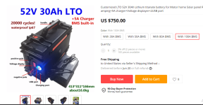
Not sure of the cost of Vruzend kits. I know it was at least $40. Also if there is something better than Vruzend that can do the same thing please let me know.

Thanks.

LC. out.

3/11/21 - 7:37 PM.

Not only is VRUZEND kits out of stock but they are expensive. It would take four or five $40 kits to accomplish anything usable.
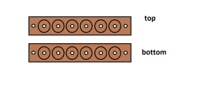
Basically unless there is a better solderless option I Will need to build something out of wood that can work. A cell holder.

Once I build it I can use bolts on either end of six cells in a row all in parallel for a 6P pack - 3 to 6S. It will hold the cells firmly together than drill small holes and countersink the nuts in the wood with a small amount of wood glue directly above and under each cell and screw the bolts in from from the outside top and bottom.

If I need more capacity I can parallel two 6P for 12P or for 3 kilowatts 18 or 24P

I thought about doing this years ago but decided against it. However I really think that if designed right it should work. Not sure if hot glue sticks to wood but already found strips of wood suitable for the top and bottom. The cells will be lined up like in the picture but will need smaller thinner strips on either side of the cells so the cells are held in place.

IMG_0022.JPG

It really is not rocket science. It is measuring accurately where to drill the holes and having about 200 small nuts and washers and having the right wood glue and a drill bit for counter sinking each nut. That and thin strips of wood for each side of the cells and gluing those strips in place.

Obviously I will need to go to home Depot for the thinner strips as well as the nuts and bolts. I can see if hot glue sticks to wood on a scrap piece. If it wont wood glue will do the trick. I will keep you all posted on any progress.

If anyone has any ideas that will work or a cheaper kit to make my life easier please post it.

Thanks.

LC. out.
 

Attachments

  • cellholder.png
    cellholder.png
    13.3 KB · Views: 564
Screw terminal batteries or prismatic
https://bmsbattery.com/65-battery-cell

New version is sold out
https://vruzend.com/product-category/battery-kits/
*Scanning through the info, no mention of max amp discharge. Remember the more you have in parallel the less amp discharge.
Also that is friction by way of a spring, so produces more heat due to higher contact resistance.
And going over bumps is even more --------------------------> Not good!


I used an older version of this with a Microwave Oven Transformer MOT Tab welder. Usually find freebies behind thrift stores as they are not allowed to sell microwaves. Take winding out, rewire, build base, I made mine out of wood.
https://avdweb.nl/popular/spotwelder/diy-spot-welder
 
Well Spot welding is an idea but with my luck will probably turn a cell into a fire cracker.

The thing is if my method works It will be very simple to remove and replace cells. The bolts on the top and bottom will have nuts to secure wires so no welding or soldering is required to add a BMS or balance plugs. It is like the VRUZEND kit in that way but much easier to assemble. You do not have inter-locking caps and springs. You can just slide the cells in and torque the bolts down top and bottom firmly but not too tight.

IMG_0025.JPGIMG_0026.JPG

Check out how simple counter sinking the nuts will be with the right size drill bit. wrapping a thin strip of electric tape around the drill bit will make sure all holes are counter sunk at the same depth. Like I said it is not rocket science here. Just basic wood working skills.

counter sunk.png

All is required is strips of wood sold at any home improvement center , a couple drill bits. Glue or fiber glass resin and 200 small nuts and bolts. And two longer bolts at each end. If designing a 10p to 16p any S pack then a bolt could be placed in the center.

The materials are like 1/10th what a VRUZEND kit would cost and practically anyone can put it together. The trick with the counter sunk nut is the correct size drill bit so the nut fits snug in the hole. (see pic below) The glue or resin will go around the edges of the nut so when screwing the bolt down the nut wont turn.

Basically you could cover all the wood with a thin coat of fiberglass resin then lightly sand and paint and will be much stronger than the cheap plastic caps.

I think I will price 3D printers. If you could 3D print out of a hard durable plastic you could have the holes for the bolts threaded and no nuts would be required on the top and bottom of the cells. Just outside on top and bottom for securing the wires.

How about we start a company and compete with VRUZEND. We may put them out of business. We could give them the option to merge with our company so we do not put them out of a job. With a decent 3D printer we could mass produce 18650 kits and make a fortune. We could sell kits as well as build and sell packs with BMSs.

Why not make some money here. It will be fairly simple for me to build some proto types when I get the ambition. :oops:

I had a similar idea before and even drilled holes in wood for custom cell holders and slid 18650 cells into the holes. that was not a good idea though as took up way too much space. With long thin strips of wood like in my diagram the cells will be in a row with no space and take up less room. The only holes will be for the bolts top and bottom.

Please let me know who wants to make some money and start a company. I know SUNDER has a 3D printer but he is extremely busy with his job. He is a hard worker. How about DA. Markz and maybe DAN and myself. We all get together and make a fortune.

Thanks.

LC. out.
 
latecurtis said:
DrKangel said:
Yes! ... Because you try to solder at max temperature! ... the rosin core (flux) is burnt off before it can work as cleaning\etching\bonding affect.

Too high temp:
evaporates flux = smoke;
tempers tip, so solder won't stick on it, preventing good heat transfer!;
burns-corrodes tip.

I really do not understand what you are saying. (yes) If it smokes and solder wont stick and it burns and corrodes tip then it sounds like either solder is counter productive or I need to adjust the heat as there is a control knob on all three of my solder irons. Two which are brand new.
Rosin core solder has a core of Rosin which acts as a flux.
You tend to use maximum heat which evaporates the Rosin before it can touch or work on the metal to clean and etch it for solder bonding. So you do need separate flux!

You need to use lower temperature with a heavy tip to create reliable solder bonds.
Too hot and tip will be "burnt" and not hold any solder.
Try lower temperature with additional flux on a new heavy tip.
1 flux new heavy tip
2 set iron to 350 deg C,
3 let iron fully heat
4 touch to solder and it will melt and flow onto tip
not hot enough?
set slightly higher and repeat
Depending on solder formulation, near 370 (400 lead free) might be optimal.

"A hot iron will melt solder immediately on contact. Whereas, a cooler iron will need to be held in contact for a while first, which might do damage to the PCB or parts.

Though, apparently, between 600°F and 700°F (~320°C - 370°C) is ideal.

Any higher and you might:

Damage components
Reduce the lifespan of the tip
Melt insulating wire
Burn off flux
Vaporize lead"

"The problem is that lead starts to vaporize when heated over 752 degrees F, (400 degrees C), and you can end up breathing in the poisonous fumes. A HEPA respirator(CK) and copious ventilation, should keep you safe."
 
I hate soldering 18650 cells. I can solder wires together but would rather build 18650 solderless kits like my posts above.

My idea should be patent. It is way better than the cheap VRUZEND with springs and too much hardware.

If we had a 3D printer we could make a lot of money. In fact I will price them. DA. you are not far from where I live.

If I get the printer I will need help running the software. I have money. I have 800 in my bank to spend and will have $2,800 coming as my wife and I both are getting stimulus check #3.

I might buy the printer myself and a bunch more 18650 cells from battery clearing house. I may need the hard plastic and material that the 3D printer requires to build the fancy cell holders for the kits. The bolts can be ordered on e bay and the holes will be threaded by the 3D printer.

We just need to decide on what connecters we will use for series connections for custom builds. We can build different size cell holders for 3S to 16S or more. 10S , 13S and 16S are popular so we can build different kits and mass produce them with a 3D printer.

Thanks.

LC. out.

3/12/21 - 3:19 AM.

Yea. I could not sleep.

I need to watch a TV show Taken. It is a series now but not same actor as the movies.

I tried to sleep with no beer but think a few wont hurt. Less than a 6 pack or 2 or 3 - 25 oz. cans.

it looks like a 3/4" drill bit will be perfect for the job and all holes will be centered. I wont need sides. Just top and bottom and about a 1/3" holes and the cells should fit in tight. At most I can wrap a strip of electric tape for a snug fit if needed. The holes for the bolts will be started. I am thinking about a thin coat of fiberglass resin. It will look like plastic cell holders then.

I will paint them black then and can get small nuts and bolts at Wall-Mart in the hardware section. They can all be 6P and can stack them for 12P , 18P or 24P. I will make a 3S - 3P for every two 6S - 6P for 15S - 12 - 24P.

Tomorrow I will ride the 20" bike with the 1,800W brushless motor to test it out to Wall Mart as if the chain fails is only a two mile walk home. I think super glue will work to secure the nuts. I can counter sink them on the out side top and bottom or the inside. It should not matter. First step is building the cell holders. Then dealing with the hard ware afterwards. Super glue may do the trick as will only need a couple drops around the nuts so they don't turn when screwing the bolts in.

Thanks.

LC. out.
 

Attachments

  • cellholder2.png
    cellholder2.png
    5.5 KB · Views: 540
  • IMG_0027.JPG
    IMG_0027.JPG
    323.6 KB · Views: 540
Could sell all your new soldering equipment to help finance your impending 3d printer. :mrgreen:
 
[youtube]8nn7EWmLs1k[/youtube]
 
https://www.toolots.com/x5sa.html?cid=10196878749&gclid=Cj0KCQiAv6yCBhCLARIsABqJTjb5DysYNGCpKLR4fz87mjcT276ZEuNZ60GVAsiK_roRMrckMksDuiAaAgvbEALw_wcB

download (1).png

A tool is only as good as the user and I have absolutely no clue how to use something like that. It looks like alien technology to me. I would love to buy it but would need someone willing to teach me how to use it.

Also does anyone know about these ?????

download (3).png

I just discovered then this morning before I went to bed. They are expensive and less capacity than high capacity ion cells but last 20 times longer. Also charge quick so on long distances could charge several small packs quickly with any AC outlet.

Please let me know what you think. I am drinking coffee right now. Was hoping for a 3D printer that could do metal as well as plastic. I need to do more research. Printing custom sprockets would be awesome. Gears for belt drives. ect.I am surprised at how affordable they are today. The only thing I wonder is how to use the design software. I never was good with software.

I would love to order the 52V LTO with the BMS below but $750 is a lot of cash. :roll: I would need more voltage for the FX - 75 - 5 motor though.

I would also love that $300 printer if I could figure out how to build plastic cell holders. 15 - 3/4" is sweet. Should be easy to build 16S cell holders if I could figure out the software. :roll:

I am starting the DIY 18650 cell holder project. The first step is measuring which will take awhile as you can see there are a lot of circles to draw. Hopefully will be able to start drilling by tomorrow.

Then I will need to install all the nuts which should go on the outside so will not have to take it apart if a nut starts spinning to re glue it. I will need to go and get the nuts and bolts today. I wont be using really small bolts as want decent surface contact but not too large either.

After that I will be cutting into 6S and 3S and then a thin coat of fiber glass resin.

Finally very light sanding and paint. After that then can install the wires and test for voltage.

Finally parallel for 6P each pack and install 6S balance plugs.

Looking at it now I get 7 - 1/4" total length and 1- 1/4" width for 6S - 1P so for 6S - 6P stacked is 7- 1/2" by 7 - 1/4" by approx. 3- 1/2" . It is not really large for 6S - 6P but two in series for 12P will take up quite a lot of space however that is the trade off for no solder and easily replacing cells with better or newer cells.

Also am considering a custom triangle rack for mounting the cell holders in the frame. Obviously each bike is different but a bike with a large triangle could in fact work. With my new jig saw and extra blades almost anything is possible.

Basically it is going to take awhile but should work perfectly. I will probably build a 10S - 6P - 60 cell pack also as I bought a BMS for 10S and 16 amps for the Bafang motors. I could run my old 10S - 10P packs but they are old and heavy. A smaller lighter pack is desirable for the Bafang motors as am running my 13S - 7P pack for the rear motor so the old 10S pack is really heavy.

Thanks.

LC. out.
 

Attachments

  • download (4).png
    download (4).png
    80.9 KB · Views: 504
  • IMG_0029.JPG
    IMG_0029.JPG
    307 KB · Views: 500
  • IMG_0030.JPG
    IMG_0030.JPG
    290.9 KB · Views: 500
As the Hub Motor Turns and the LiPo Fire Burns.

I tested the 1,800W brushless motor tonight for a Wall-Mart trip. I finally got the tension on the chain perfect. The noise it was making before is less than half as loud. It is actually quiet now for a chain drive.

However I believe that at full throttle it will fail. Something will break. The torque of that motor at 1,500W or 2 horsepower will snap almost anything short of a professional welding job. Yes Mary's son has a welder but honestly I would like to have it professionally installed. No wood or steel adjustable straps but thick steel and professional welds.

Anything short of that I do not think will work. 10 to 15 mph with light throttle is fine. Not too sure about 20+ mph and did not try it tonight. Possibly tomorrow. My guess is the motor is capable of 35 mph but not without being welded to the frame with angle steel.

Since I do not want a chain falling off at 30+ mph the only other way to test it is up a steep hill. However there are not a lot of hills. Basically since I spent a lot of time and effort finally getting it so I can ride it normally like the other 20" bike with the hub motor on the back I would rather not test my chain mount by pushing it to it's limit. I will be content right now just riding it < 20 mph. At least for awhile. It is a back up for my 20" Turbo with the hub motor on the back.

I went to Wall-Mart for small bolts. I will succeed believe it or not building 18650 cell holders and will be able to use small nuts and machine bolts to make the connections. No solder. Yea I know you all have your doubts but the turning point was today when I broke out the corner molding.

I also will need to order some 3S balance plugs. I have a 10S - 16 amp BMS so will build a 10S - 6P - pack. Then a 3S - 6P so I can run 13S.

Since I have more than 20 - 6S balance plugs I will be building a 4S and a 3S pack for each 6S pack so can run all three in series for 13S or just run the 6S and 4S in series for 10S. All can be charged by either of my LiPo chargers.

Basically measuring and marking the holes to drill are the only challenge so the more I do the better and more accurate I will get. I also need to clean any old flux off the end of the cells. The bolt will need a clean connection but other than that it should be really straight forward and will not take up much more space than factory built packs.

Cost of construction is also cheap as 8 feet of that corner molding is like a couple bucks and 24 nuts and bolts and a buck. Only a couple drops of glue for each cell so that glue should be good for a dozen packs or so. I did not want to use much anyway in case I want to replace the cells.

The only thing is I need to use a small drill bit to start to not crack the wood and make sure it is dead center or really close. If it does crack glue can hold it together but a little fiber glass resin will be about 50 times stronger. It is will take awhile but at least I know it is possible to do.

Thanks.

LC. out.
 

Attachments

  • IMG_0031.JPG
    IMG_0031.JPG
    316.6 KB · Views: 449
  • IMG_0032.JPG
    IMG_0032.JPG
    445 KB · Views: 449
  • IMG_0034.JPG
    IMG_0034.JPG
    270 KB · Views: 449
  • IMG_0035.JPG
    IMG_0035.JPG
    423.5 KB · Views: 449
  • IMG_0036.JPG
    IMG_0036.JPG
    402.1 KB · Views: 447
  • IMG_0037.JPG
    IMG_0037.JPG
    415.7 KB · Views: 442
As the Hub Motor Turns and the LiPo Fire Burns. test #1. - 1S - 6P.

https://www.youtube.com/watch?v=wDNhFs0vs5k


IMG_0045.JPG

Each day I should be able to increase speed. Hopefully in a week or so I can build 4 or 5 a day.. Looking at 10S - 6P for the Bafang motors.

Then 10S - 10P and 3S - 10P for 13S - 10P after that,

Thanks.

LC. out.
 
Status
Not open for further replies.
Back
Top