new eZip motor

Status
Not open for further replies.
Nope, the motor, being much higher rpm, likely has more drag, with the chain and gears being additional drag!
Still, with the 2 different voltages, I still rate The 26" Dual suspension as #1.

I do not see how. The motor sprocket is like a freewheel. The chain don't even move unless the motor gets power. I pushed both bikes and the hub motor on the back is a lot more drag.


Well what about that vender. ?????

Did you see those deals ????

Is it a scam. ????

I would really like to know ??????


Please let me know.

https://www.xsqwiy.com/index.php?route=product/search&search=hub%20motor%20


Thanks.

LC. out.
 
Oh, you didn't mention "like a freewheel".
Buy something and find out, just be sure to pay with paypal!
 
Oh, you didn't mention "like a freewheel".
Buy something and find out, just be sure to pay with paypal!

The Currie is running 25H chain and 80T freewheel sprocket.

Gearing is for 32 mph at 3,000 rpm. It did 28 mph in the video I posted.

The weak link is the brush controller. The part of the video that shows the power meter proves that.

download (4).png

Maybe not.

34.15V is a lot of voltage SAG from 40 or 39V.

Is that normal for LIFEPO4 ?????

I used the 42V charger to charge them in series. Only one single cell was a little low so used that wood strip for the first time and the Skycharger on LiLo mode. 3,6V - 1S as it would not charge on LIFE mode. It read FULL after 5 minutes and shut off.

I charged it at 1S - 0.5A as charging with balance wires but the cell charged in about 10 minutes. I will check all the cells tomorrow.

For the power modules and LTO I think I should use a BMS.

If I order a factory wire front basket for the front of the e bikes I want to run LTOs then I could build a 10S pack for the frame where I have been mounting them and a 10S - LTO pack in the front basket.

To counter some of that weight a rear DD hub or chain and rear cargo basket for my chain , padlock , tools and any cargo.

That is the plan. Two 10S - LTO packs each with a BMS. The same exact BMSs so they will work in series.

Again. I do NOT know the standing voltage of LTO - AFTER receiving a full charge so will go with 2.5V

10* 2.5V = 25V in series 20S will be 50V. Great for the 26" 48V - 1,000W motor. Wont work for the Bafang in the front.

I do not think that web site is legit. No way they would sell stuff that cheap. I would like to get a 26" rear DD for the rear of the 26" dual suspension and put the front hub motor on the front where it belongs.

the new rear motor would have the sensor wires hooked up but could still use a single throttle as long as both are 3 wire. The sensor less controller for the front will hesitate a second awhile the rear kicks in instantly. That should avoid front wheel spin out and broken forks.

I just need a really good deal on a rear 26" direct drive under $200 which I have not seen except for that scam site.

Please let me know.

Thanks.

LC. out.
 

Attachments

  • download (5).png
    download (5).png
    145.5 KB · Views: 875
They probably are doing what BMS Battery, Cyclone-TW and other websites do.
Cheap cheap product price to get you interested.
Then a high s/h price to get back price on product.
$75 for the kit and maybe $200 for s/h I'm not abut to look at the pic you attached or click on the website, I dont care. $200-250 is the price, yescomusa and its affliate and other ebayers.
 
One of the stupidest things yet.
A 36V geared hub dragging along an unpowered 48V 1000w DD hub, max efficiency might only near 50% ? Resistance likely to be something similar to very soft tires or going up hill!

I had to hash that over awhile.

Not really.

That is my answer as a geared hub motor has good torque from a dead stop to around 20 mph. The Bafang. It is very evident with Dual motors for the light 26" Diamondback Outlook.

0 to 15 mph on flat or decline the Bafang will do well even with some drag. However I use two throttles. I can take off with the rear hub or the front. On flat it don't matter. Just a little hesitation starting with the rear but not much.

The trick is using both motors as if a slight decline or flat the Bafang is best under 15 mph or peak torque. There is no dragging an unpowered motor. Not when you have gravity and or momentum in your favor. A slight decline where 17 to 21 mph the Bafang SOL0 is most efficient. I take off with the rear and get up to 12 14 mph and maintain it with the Bafang but

15 to 26 mph both throttles. I phase in the rear and for around 20 mph cruising less than half throttle both throttles. You can feel it if the motors are working together.

After 20 mph the gearing ends for the Bafang so no need for the throttle. Just use rear DD drive.

The rear motor could use a few extra amps if possible. 54 to 56V would be perfect at 30 amps.

Other than that I do not need a direct drive on the front. I will do a video to prove it. that bike runs good. I think I already did a video. I will look.

https://www.youtube.com/watch?v=nl9t-TJH9C8&t=3s

A 36V geared hub dragging along an unpowered 48V 1000w DD hub, max efficiency might only near 50%

I think the video proves otherwise.

Two motors are always better than one for the simple reason double chance of getting home. Like having two motors on an airplane.

I spent a lot of time building that bike. I had the bike shop re lace a new rim and got sensor less controller as never had one and was curious. it did work with the sensor wires as I soldered all new wires all the way to the inside of the motor. I wanted to see if the Greentime controller worked better but think maybe a little.

It ran the best when it was new on 12S LiPo. It is amp hungry. Power hungry. The same thing.

I used the 13S - 20Ah pack I bought about 18 months ago or so for both bikes.

The best most efficient motor out of the two is the 1,800W brushless chain drive. That is for power and top speed and performance. Not for distance efficiency or range.

The Giant Roam with the 700c - e bikeling 500W front and rear 26" 500W. My best e bike.

The rear is good for take off just like the 26" dual suspension but the front is geared higher so the rear is only required for take off or 0 to 5 mph and up hills or inclines.

Also it will have 21 pedal gears. For < 10 mph pedal will work. No drag with geared hub motors. 0 drag + pedal + super efficient 500W GEARED front hub. + the 500W rear AND pedal assist up hills and declines.

I think I should work on the Giant Roam. I got the 12S LIFEPO4s properly balanced. I am not spending any money this month. I need to give my wallet a break. No more stimulus money.

Thanks.

LC. out.
 
latecurtis said:
Gearing is for 32 mph at 3,000 rpm. It did 28 mph in the video I posted.

The weak link is the brush controller. The part of the video that shows the power meter proves that.

file.php


Maybe not.

34.15V is a lot of voltage SAG from 40 or 39V.

Is that normal for LIFEPO4 ?????
19Ah battery?
40A is 2C+
2C+ discharge will sag noticeably,
IFR26650 3.2V 3200mAh (Pink)-Capacity.png
but your "cold solder joints" can induce substantial IR = sag, into your build.

See - [color=#000000]Hand Soldering [/color] and read carefully "cold joints"
 
but your "cold solder joints" can induce substantial IR = sag, into your build.

I have IR tester.

I can measure that.

There has to be a way to prove my cold solder joints are a factor.

?????

I need to know what a healthy spot welded or factory built 6S - 5P - 26650 pack is supposed to be in IR.

I can then measure my pack and compare the numbers.

Please let me know

Thanks.

LC. out.
 
Compare IR from bare cell contact points and from soldered wires.

See - Hand Soldering and read carefully "cold joints"
 
Compare IR from bare cell contact points and from soldered wires.

See - Hand Soldering and read carefully "cold joints"

Well here's what it looks like.

download (4).png

My readings really do not make sense.

IMG_0967.JPGIMG_0968.JPG

That is measured iR.

HOWEVER the higher number is the pack I soldered with the WELLER. Not the 60W iron where I heated the cells up excessively.

That is why it does not make sense. With the Weller when I touched the cells right after soldering they were barley warm. They were hot as hell with the 60W iron.

A lower IR is supposed to be better right ?????

I do not think there is anything wrong with my packs.

My guess is normal chemical reactions according to heat , charge and discharge. Perhaps heating up the cells lowered IR.

I think IR is a fallacy. It is BS.

My LIFE packs are rocking.

Now it is time for someone or anyone to acknowledge that fact.

Thanks.

LC. out.
 
Alex Pope would be so proud!
Indeed, you prove to be the living embodiment of his greatest works.
 
DrkAngel said:
Compare IR from bare cell contact points and from soldered wires.

See - Hand Soldering and read carefully "cold joints"
Hand soldering
A tube of multicore electronics solder used for manual soldering

For attachment of electronic components to a PCB, proper selection and use of flux helps prevent oxidation during soldering; it is essential for good wetting and heat transfer. The soldering iron tip must be clean and pre-tinned with solder to ensure rapid heat transfer.

Electronic joints are usually made between surfaces that have been tinned and rarely require mechanical cleaning, though tarnished component leads and copper traces with a dark layer of oxide passivation (due to aging), as on a new prototyping board that has been on the shelf for about a year or more, may need to be mechanically cleaned.

To simplify soldering, beginners are usually advised to apply the soldering iron and the solder separately to the joint, rather than the solder being applied directly to the iron. When sufficient solder is applied, the solder wire is removed. When the surfaces are adequately heated, the solder will flow around the workpieces. The iron is then removed from the joint.

If all metal surfaces have not been properly cleaned ("fluxed") or brought entirely above the melting temperature of the solder used, the result will be an unreliable ("cold solder") joint, even though its appearance may suggest otherwise.

Excess solder, unconsumed flux and residue is sometimes wiped from the soldering iron tip between joints. The tip of the bit (commonly iron plated to reduce erosion) is kept wetted with solder ("tinned") when hot to assist soldering, and to minimize oxidation and corrosion of the tip itself.

After inserting a through-hole mounted component, the excess lead is cut off, leaving a length of about the radius of the pad.

Hand-soldering techniques require a great deal of skill for the fine-pitch soldering of surface-mount chip packages. In particular ball grid array (BGA) devices are notoriously difficult, if not impossible, to rework by hand.

Cold joints
An improperly soldered 'cold' joint, where the wire was not sufficiently heated
Broken solder joints on a circuit board. The joint on the right, although unbroken, has separated from the board.

Various problems may arise in the soldering process which lead to joints which are nonfunctional either immediately or after a period of use.

The most common defect when hand-soldering results from the parts being joined not exceeding the solder's liquidus temperature, resulting in a "cold solder" joint. This is usually the result of the soldering iron being used to heat the solder directly, rather than the parts themselves. Properly done, the iron heats the parts to be connected, which in turn melt the solder, guaranteeing adequate heat in the joined parts for thorough wetting. If using solder wire with an embedded flux core, heating the solder first may cause the flux to evaporate before it cleans the surfaces being soldered.

A cold-soldered joint may not conduct at all, or may conduct only intermittently. Cold-soldered joints also happen in mass production, and are a common cause of equipment which passes testing, but malfunctions after sometimes years of operation.
 
Excellent info
Is that in your footer links?
--Index - Homemade Battery Packs - Updated - December 2019--


The link in your footer named --Endless Sphere Wiki-- is appropriate for eZip thread.
:lol:


DrkAngel said:
 
Well I was going to pay DA to build it for me but he declined. I would have paid $100 labor and covered the $30 each way shipping via FEDX.

The bottom line is I did it myself and the pack is working. Some of the solder joints were re - soldered two and three times and the cells heated up before I got the Weller.

The Weller was supposed to solve all those problems DA. listed as it is the proper temperature for wetting the solder so it is not a cold solder or something else. One pack of 30 cells for 6S - 5P was done with the Weller and one was not but testing them the IR is higher on the pack soldered with the Weller.

However both packs run , charged and balanced. We can speculate which cell banks are bad or how the packs might fail in the future, Yea we could do that but Frankly I would just rather run them. If it is not broke then don't fix it. I am not removing those packs from the boxes unless I have a real good reason to do so. Not because there is some voltage SAG.

I just checked all the cell banks in both packs and are all 94 - 98% except one cell bank it at 92%. I did not run them today.

However it is all the more reason to build LTO packs now as no solder or spot welding is required. Two 10S packs will work if one is on the frame and the second in a front basket. I will get 50V or a little more. It sounds like a good idea to me.

I just will not be able to run any Bafang motors at 50V. I wont be able to run the 26" Dual suspension at all as with two 10S - LTO packs there will be no room for the 12S LIFEPO4 packs. I can still run the front Bafang with the 12S LIFE packs and put the 13S - 20 Ah pack in a front basket. But once that 13S pack fails I got no way to run the rear motor

unless.

I use a step down DC converter. They make those as well. There should be one that will do 48 - 60V and put out 36 to 42V. I wont be needing it for awhile though as long as the 13S - 20 Ah pack works. It is sitting at around 3.7V per cell. I really don't need it unless I run the 20" Turbo or the 26" Dual suspension. I will charge to 4.@V per cell the night before I run it.

Once I build the 50V LTO pack I can run the 20" Turbo , The 1.800W brushless motor and maybe even the 3 kilowatt motor. Not sure as never got a straight answer.

Looks like I will need to order two 10S - LTO - BMSs and get to work building. I just do not know which BMS to use so will post some. I also need the ring terminals as I do not know the exact size bus bars for those.

I have 10 gauge wire for the series connections. It wont be good for the 28 kilowatt SEVCON controller though. That sucks as will have to completely rebuild the LTO packs but will need 80V anyway so I guess it don't matter. I will just need to un screw the connecters. I wont have to remove the LTOs from the boxes I build to hold the cells together.

I will post the BMSs I intend to use before ordering so I get the right ones. They must work in series and will go with 80 amps I guess. The 3 kilowatt brushless controller is rated at 70 amps. I will need to take a ride to Home Depot and get some more 1/4" plywood cut. I used the 26" dual suspension before with a milk crate attached to the rear rack.


I checked and a 80 amp BMS for LTOs will cost at least $50 for one.

And what is this crap about needing an active balancer for your LTO, are they defective? The only reason for an active balancer would be as a band-aid on a defective battery till you can fix it. Adding to a good battery ... it will do absolutely nothing. Like LiFe, LTOs are auto balancing during charge, even when somewhat defective in some different ways.

OK. If I can save a lot of money running LTO AND the 13S power modules with no BMSs then how about externally balancing 13S and 10S with my 7S 5 in 1 cell balancer. No idea if it came with a 7S balance plug though. I might need to see about ordering them if they exist.

It would be easy if I connected a 6S and a 7S balance plug to the bolt terminals. Then just plug in a the 7S and one of my 6S balancers. I will need to unhook the parallel connection for the power modules though until each side is balanced.

Please check out the pictures below as if it is possible to externally balance with what I got and even charge a single cell that is a little low like I did yesterday it could save me at least a couple hundred bucks for BMSs or active balancers.

Can I balance 13S with two balancers at the same time ? Or will I need to balance 7 cells then unhook it to balance the other 6 cells ; Or is the whole thing just a bad idea ????????????????

If that will work then I can just get to building a box for the power modules as well as the LTOs.

Please let me know.

Thanks.

LC. out.
 

Attachments

  • IMG_0974.JPG
    IMG_0974.JPG
    206.3 KB · Views: 771
  • download (5).png
    download (5).png
    145.5 KB · Views: 771
  • PM13.png
    PM13.png
    22.5 KB · Views: 770
  • BPM.png
    BPM.png
    26.8 KB · Views: 770
latecurtis said:
The bottom line is I did it myself and the pack is working. Some of the solder joints were re - soldered two and three times and the cells heated up before I got the Weller.

The Weller was supposed to solve all those problems DA. listed as it is the proper temperature for wetting the solder so it is not a cold solder or something else. One pack of 30 cells for 6S - 5P was done with the Weller and one was not but testing them the IR is higher on the pack soldered with the Weller.
Looks like every one of your solderings are cold solder joints!
I did link to, then quote, how you seem to have precisely followed the instructions on how to create cold solder joints.
Not any problem with tools or materials, just basic operator error.
 
The LIFEPO4 packs work. Cold solder or hot !!!!! If they stop working then I will cross that bridge.

I can get to each solder joint. I built it like that. All I need to do is take the packs out of the boxes. If the time comes for that I will deal with it then.

I am moving on.

I was wondering about my question about balancing 13S - Lion and 10S LTOs.

Will my diagrams work and how will I go about doing it. Balance 7 and then the other 6 or use two balancers ?????

For the LTOs I might need a external LTO balancer. Not sure if my balancers can balance LTO ???????

NOT an active but external like my 7S and 6S external balancers. Do they even make one for LTOs ?????????????????

Please let me know.

Thanks.

LC. out.
 
markz said:
How long has this battery dilemma been going on?
Seems like forever.
Well, took more than a year to pry LC away from Lead acid batteries ... but then he relapsed this year, even using SLA to charge Lithium. So, some leaps but plenty of stumbles... ?
[youtube]nSw2T_ceyeM[/youtube]
 
by DrkAngel » Sep 14 2021 8:41pm

My mother did animal rescue work, mostly have them fixed. Bad part was she has around 18 cats around here. Have a good idea how cats act. They are all different.

Now that video is funny, had me rolling. Thanks for the laugh.
Peaches.JPG
This is Peaches!
 
I want an external balancer that can do all three battery technologies I am running.

Lion , LIFE and LTO.

I want an external balancer I can just plug in to any of those packs when needed and will balance in minutes , not hours.

Unfortunately only 6S , 7S and 8S external balancers exist and sometimes take hours to work. So a BMS or active balancer is the only options.

HOWEVER !!! If I could use one active balancer externally for all three battery types like an external 6S or 7S balancer and balance the pack when NOT running it then why does DA. think an active balancer is such a waste of money ?????

It is established that at least one of my LIFEPO4 packs have a low cell bank that seems to self discharge sometimes. It don't mean I have to tear the packs apart and re solder everything. That just seems absurd.

If I can attach the correct balance plug extensions into each pack : 6S , 10S LTO or 13S Lion then plug any of those packs that need balancing in that active balancer they should be balanced in a few minutes and ready to run.

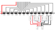
Here is the active balancer I wish to convert to external balance via. the correct balance plugs from the different packs.

download (10).pngdownload (11).png


Notice the bottom pic where it says to weld those two terminals together for LTO. Will a plug or a switch work as I do not want to just balance LTO exclusively. I am sick of spending money so why I want to only buy one balancer instead of expensive BMSs for every pack.

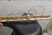
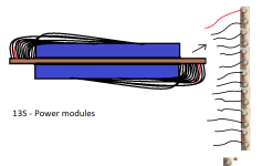
This is e bike related and legitimate questions. My intentions are to solder a 13S balance plug to the 13S power modules. A 10S plug to each 10S - LTO pack and a balance plug to any other future packs and to my 6S LIFE packs if needed but probably wont need to as I have two 6S balancers as well as that 7S and two 6S LiPo chargers to deal with my 6S - LIFEPO4.

However an 18S LIPO4 spot welded in the future sometime seems like a great idea for the 3 kilowatt brushless controller so I can get full power or 3 kilowatts to the motor. Not sure if they sell an 18S balancer though. But could go with two 9S LIFEPO4 packs or spend a few extra bucks for an 18S external balancer if there is one.

Please let me know. LTO as well as active balancers is way over my head. Up until now I only dealt with 6S balancing when needed. But my BMSs failed. There is a good chance I could still save that 10S - 4P Laudation pack as I unwrapped it and can test cell banks and perhaps use that active balancer on it as well.

I did not drink last night and am up early. Thinking about going to the Home Depot for 1/4" plywood so I can start building custom boxes for the 13S power modules as well as two 10S - LTO packs.

Please let me know if I can use that balancer externally by soldering 10S and 13S balance plugs to the packs. Also I think it is Bluetooth so when I get up later as I am laying back down now I will search for 18S and Bluetooth as would be super cool to sit here on my laptop and see every cell balance or at least on my smart phone.

There is one.

https://www.aliexpress.com/i/1005001389756298.html?af=1424725&afref=&cv=47843&dp=826be8fc1d9af45000e41457849bd65c&mall_affr=pr3&utm_campaign=1424725&utm_content=47843&utm_medium=cpa&utm_source=admitad&aff_fcid=7cebfad6cae642dbb7ab504cb44da6b9-1631704878659-00630-_ePNSNV&aff_fsk=_ePNSNV&aff_platform=portals-tool&sk=_ePNSNV&aff_trace_key=7cebfad6cae642dbb7ab504cb44da6b9-1631704878659-00630-_ePNSNV&terminal_id=9581d40076cb4e08aa1132a6f5058123

Did not see the Bluetooth though. I want that.

https://www.aliexpress.com/item/1005003125644284.html


download (12).png

I like that one above way better than the others. It is fully enclosed like a regular 6 or 7S external balancer and don't have two different plugs which is confusing. It should work better as an external balancer like I want. It is worth the extra $$$$$.

https://www.aliexpress.com/item/1005003104573871.html?spm=a2g0o.detail.0.0.2cf9175c7M0RcL&gps-id=pcDetailBottomMoreThisSeller&scm=1007.13339.169870.0&scm_id=1007.13339.169870.0&scm-url=1007.13339.169870.0&pvid=0e549d6c-3ba0-4058-8630-51c21ff2b6bc&_t=gps-id:pcDetailBottomMoreThisSeller,scm-url:1007.13339.169870.0,pvid:0e549d6c-3ba0-4058-8630-51c21ff2b6bc,tpp_buckets:668%232846%238112%231997&&pdp_ext_f=%7B"sceneId":"3339","sku_id":"12000024110134304"%7D

That one is cheaper. I need to do more research but at least you all know what I am looking to do and why.

I think DA said ""One BMS to rule them all" for the power modules.

I want one balancer to rule them all. Each and every pack that I own.


Please let me know.

Thanks.

LC. out.
 
Well, if you truly must put a band-aid on your defective battery builds, I guess you should be made to pay the price.


Rule-Step #1 in any battery build should be to test for and remove self-discharging cells!
Simplest and easiest step too! IMO
 
download (1).pngdownload.png

Well. I ordered those. My budget would not allow the one DA. posted.

One is for 10S - LTO

The other is for the 13S power modules.

I am only using them when I am not running the packs. I will be using them as external balancers.

I will continue using my 7S balancer and 6S balance chargers for the LIFEPO4 packs.

If the 3 kilowatt brushless controller will work with the power modules I wont need a third 6S - LIFE pack for 18S. But if it wont I will order one more box of 26650 cells and solder another 6S LIFE pack for 18S and 60V.

I only know how to cold solder I guess. I checked each solder joint before combining for 1S - 5P for each cell bank and I got a voltage on each cell so am not even sure what DA. is talking about. It is just over my head.

The WELLER is a very hot iron and the solder was in a molten state and changed color when it cooled like it is supposed to. I still do not know what this cold solder is even about. I may never figure that out.

I still need ring connecters for the LTOs. I have 10 gauge wire which will work for now. I will need to upgrade that if I decide to order more LTOs for 80V and the FX - 75 - 5 SEVCON controller.

I can probably pick those up at Home Depot when I get the 1/3" plywood.

I ordered cheap balancers for a good reason as LIFE as well as LTO are not near the energy density as other chemistries so they lack in capacity. It looks like my 12S LIFEPO4 pack is about the same at 10 or 12 AH - SLA. It is rated at 19 AH but not even close from what I see.

My LTOs are supposed to be 18 AH so could only be = to 10AH - SLAs as well. The only logical solution is very fast portable charging to get me up and running in minutes , NOT hours.

I found one for the LTOs. 20S - LTO is around 50V so will that charger below work ?????

https://www.amazon.com/Eseegoo-Compatible-Yamaha-Battery-Charger/dp/B08P341HX1/ref=sr_1_18_sspa?dchild=1&keywords=48V+20+amp+battery+charger&qid=1631741151&sr=8-18-spons&psc=1&spLa=ZW5jcnlwdGVkUXVhbGlmaWVyPUExU1lQNVpHUU9ZSVZSJmVuY3J5cHRlZElkPUEwNTg4NDk2MVEwN0VGNktNNzRSRCZlbmNyeXB0ZWRBZElkPUEwMDcwMTIwMUJJQTdIMENLSkZMUiZ3aWRnZXROYW1lPXNwX2F0Zl9uZXh0JmFjdGlvbj1jbGlja1JlZGlyZWN0JmRvTm90TG9nQ2xpY2s9dHJ1ZQ==

Thanks.

LC. out.
 
latecurtis said:
I only know how to cold solder I guess. I checked each solder joint before combining for 1S - 5P for each cell bank and I got a voltage on each cell so am not even sure what DA. is talking about. It is just over my head.

The WELLER is a very hot iron and the solder was in a molten state and changed color when it cooled like it is supposed to. I still do not know what this cold solder is even about. I may never figure that out.
Did you not read the link, or my posting from the link?
It is pretty clear in explaining!

latecurtis said:
Well. I ordered those. My budget would not allow the one DA. posted.

One is for 10S - LTO

The other is for the 13S power modules.

I am only using them when I am not running the packs. I will be using them as external balancers.
Big question mark! The 13S power modules came with their oem balance board already attached, why would you buy an additional 1 for them?
 
Big question mark! The 13S power modules came with their oem balance board already attached, why would you buy an additional 1 for them?

https://www.youtube.com/watch?v=8nn7EWmLs1k&t=331s

Because the guy in that video did. He said it was NOT a proper BMS. He said the board was junk and I thought it might short out. I did not know that it would balance the pack. It is too late as I threw out those boards. I watched exactly how he removed the board and did it also.

I still plan on using bolts for terminals so I can charge a single low cell. I plan on also hooking up a 13S balance plug to the terminals so I can plug directly in the active balancer.

Untitled.png

I will need a 48V - 15 amp charger for 20S - LTO and a 36V 15 amp for 12S LIFEPO4. Both battery chemistries are low density and limited capacity like 10 to 15 AH - SLAs so will need fast portable charging. I found those but will keep looking as need the best bang for the buck.

Thanks.

LC. out.
 

Attachments

  • download (4).png
    download (4).png
    110 KB · Views: 673
  • download (5).png
    download (5).png
    117 KB · Views: 673
Status
Not open for further replies.
Back
Top