New Puma Controller Lid Off

knoxie

1 MW
Joined
Jan 3, 2007
Messages
2,498
Location
UK
Hi

Mark at Team Hybrid sent me a new new controller today for inspection and test, it is similar to the one I had on test last week but it is a little different, it is a 36V 40A 72V 25A controller.

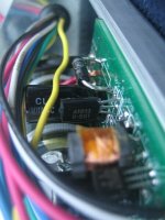
The controller is well made and a nice simple design, the casing is neat and makes it really quick to get in to, you can just pop the 8 screws and its open. This controller is using IFRB4310 fets which is good news for you power users out there! they are also employing the tab washers and a continuous insulating strip.

There is 1 x main power capacitor on board, the other chip numbers have been scrubbed off in usual Chinese style! (I do find this amusing considering the Chinese take on copyright infringement) anyway! ha ha its all bolted together in to a nice box.

There is plenty of room inside the case to add other things, a nice foam gasket would be a nice touch to help with the IP rating of the enclosure.

Changing blown components looks a lot easier than on the xlyte controllers, overall soldering quality looks good.

Mark will be stocking these for Xmas, he also has 15 or so of the BMC stamped pumas like Deecannios and Jozzers, I think they are all rear wheel only, he is putting them out for quite reasonable prices at the moment so contact mark at http://www.teamhybrid.co.uk if you are interested in getting one.

I will do a full test of this controller shortly, it will be similar to the other one of course but may offer a little more grunt.

Still its nice to have options other than the rather fragile at times Xlyte controllers, need to put some high voltage miles on these controllers before I can make a fair assessment though really.

Pictures to follow

Cheers

Knoxie
 

Attachments

  • img_8305_std.jpg
    img_8305_std.jpg
    53 KB · Views: 4,901
  • img_8306_std.jpg
    img_8306_std.jpg
    52.8 KB · Views: 4,892
  • img_8304_std.jpg
    img_8304_std.jpg
    48 KB · Views: 4,875
  • img_8303_std.jpg
    img_8303_std.jpg
    74.2 KB · Views: 2,938
  • img_8302_std.jpg
    img_8302_std.jpg
    55.3 KB · Views: 4,854
  • img_8301_std.jpg
    img_8301_std.jpg
    77.2 KB · Views: 2,942
its really refreshing to see some well designed controllers on the market :) that one looks the treat :) perfect for 72v of lifepo4 power :)

Its the only controller / motor i'll be running on the next bike.

keep up the good work knoxie! you're an inspiration. :D
Take Care,
Haydon
 
The7 said:
Seems that it uses 9 Fets! Strange!
Why not 6 or 12?

That is strange!

I wonder if at least one of them is a voltage regulator. Then what would the other ones be?

Two low side, one high side?
 
I'd prefer to see taller fins on the case. :?
 
TylerDurden said:
I'd prefer to see taller fins on the case. :?

Why? Either it can dissipate the heat at a fast enough rate, or it can't. With better FETs, un-finned xlyte controllers operate fine at much higher wattages. The efficiency of the controller is what matters.
 
I've got a couple of these here too, one is a 36-48v 25A, the other is 36-72v 40A-20A (Is yours really 40A-25A knoxie?).
Both seem to have the 9 fets, I didnt think any were regulators/thermostats, but I've left them at the workshop and will need to check tomorrow.
They are a fair bit lighter than the x'lyte 35 or 40A controllers, thank god! (the old one weighs more than 100wh of A123cells!)
I'll have both wired in bikes over this weekend, pending a wheel rebuild on the newest motor (250 RPM version of Pauls last test)
I'll try to clock up some miles quickly at higher voltages on the 72v version, just to be sure before Mark bulk orders, the 48v controller will be put in a chopper and ridden by a friend with a fair commute to work everyday.
I'll post some results after the weekend, hopefully with good news:)

Good luck Knoxie...if these come off we will have PUMA'S galore for Xmas :twisted:
 
Hi

Yes they do the job thats for sure, I am not dissing the xlyte controllers but I have had so many of them fail on me it hurts! and these off the shelf have not failed so far and I have run them at 80V+ so they do look good, this one does seem to have 25A 72V written on it, the case is substantial, it is finned, I cant see it getting even the slightest bit warm, those fets have a low on resistance as well.

Jozzer you will probably get to test these before I do as I am mental busy but will drop on to it as soon as I can, the ease of access and the simplicity of the controller is what I like, they are also a little kinder on the batteries, 72V 25A is enough abuse for those little pumas unless you fit steel gears! and of course these controllers can be hacked for more power, one step at a time for now though.

I found the controller drove the Puma slightly quicker than the Xlyte controller and it seemed to be more efficient as well although I never did test this in the end :roll:

Keep checking back, one of us should have some luck, Mark is very keen on keeping stock of the Puma and the controller contrary to the popular belief that he was tucked in tight with Matra, he needs to keep a powerful motor for his disability products.

Knoxie
 
xyster said:
TylerDurden said:
I'd prefer to see taller fins on the case. :?

Why? Either it can dissipate the heat at a fast enough rate, or it can't. With better FETs, un-finned xlyte controllers operate fine at much higher wattages. The efficiency of the controller is what matters.
Extra measure of protection. The heat is what kills 'em.

The efficiency of the controller varies with duty cycle. The real litmus test, is how the unit performs in its worst-case scenarios: high wattage, 50% duty cycle. That's where you can see major losses and heat-gain.
 
Hehe, to be fair, I think our controller woes started with the Puma Motors rather than bad controllers. I blew 3 controllers that had survived all kind of abuse on x'lytes all within moments of wiring them to the puma's, one of them at only 48v too.

Its great news Marks going to keep on this project, these motors are great, and now with justins upgraded controllers on the way and Marks controller with 4310's we should have few problems in the future I hope.

I'll keep an eye on the controllers temperature, I suspect heat transfer away from the fets will be much faster than on the x'lyte controllers, since the fets are mounted directly to the outer casing, rather than fixed to a plate which in turn has to transfer the heat through a thick layer of horrible heatpaste. I hope this will counter the reduced thermal mass of the puma controller, otherwise thermal runaway could still be a problem under extreme duress...
 
Jozzer said:
Hehe, to be fair, I think our controller woes started with the Puma Motors rather than bad controllers. I blew 3 controllers that had survived all kind of abuse on x'lytes all within moments of wiring them to the puma's, one of them at only 48v too.

Its great news Marks going to keep on this project, these motors are great, and now with justins upgraded controllers on the way and Marks controller with 4310's we should have few problems in the future I hope.

I'll keep an eye on the controllers temperature, I suspect heat transfer away from the fets will be much faster than on the x'lyte controllers, since the fets are mounted directly to the outer casing, rather than fixed to a plate which in turn has to transfer the heat through a thick layer of horrible heatpaste. I hope this will counter the reduced thermal mass of the puma controller, otherwise thermal runaway could still be a problem under extreme duress...

To be completely fair - this was on the old style clyte controllers -not the new 4310 based ones. I will eventually try mine on a puma ... eventually.
 
Some interesting info, the 72v version does indeed have 9 irf4310 FETs 3 per channel), the 48v version however has 1 4310 per channel, and 2 75542P per channel. Any thoughts on this Fetcher/anyone?
Theres a few handlaid traces in both versions I have, i'd like to see these improved, and the board is only fixed to the case via the MOSFET's, leaving the other side of the board free to flop up and down a little, this too will need sorting (both easy fixes for the final version).

Mark wanted me to investigate adding a current control pot to the unit, again Fetcher, if you have any idea where/how this would need connecting...
Unfortionatly my woman has run off with my camera for a few weeks, but perhaps you can see enough from Knoxie's photo's to have an informed guess...or we can poke him to take some more pics of the relevant parts... :lol:

More soon...


Steve
 
I can't really tell from the pics posted. A shot of the entire top and bottom side of the board would be helpful. Also if any of the chip numbers are visible, it would be good to know them.

The current limiter circuit must use a shunt and amplifier of some sort. This means there has to be a way to adjust the limit.
 
Thanks Fetch..
Indeed there is a shunt, as per X'lyte. Unfortionatly all the chip numbers have been ground off :?
Hopefully Knoxie will have some time to take some more piccie's...or I'll manage next week when my cam's back.

Whats behind the mixed fets in the 48v version do you think? Purely to save a few dollars? looks like the voltage limit is 80v on the other fets, so I imagine the 48v version is good for a 60v pack at least..


Paul, do you have any info on the wiring? Do the phase colours now match the motors? Or do we still need to cross wire as before with the x'lyte controllers?
 
Hello

I can take the controller apart again and post some more pictures if it helps, I couldn't see a busbar anywhere, they must be limiting the current based simply on the input voltage? When I tested the controller before it was ice cold and didn't get warm at half the duty cycle? I don't see heating being an issue I really don't.

Phase connections have changed according to Mark, try colour to colour first and then swap them about, using your meter you should be able to find the working combo quite quickly, make sure the no load amps is no more than 2-3A though, you could easily pick one of those high speed high no load amp configs!

Right got some snaps done, it does have a busbar! check the photos also the phase connections I used were as shown on the plug, try those first, should be fairly easy to add current limiting or at least add another 10A or so! ha ha, 50A at 37V!!

Heres the close ups, some are a little shaky, too much Joe and fading light makes for tricky photography!!

Knoxie
 

Attachments

  • img_8307_std.jpg
    img_8307_std.jpg
    21.8 KB · Views: 4,654
  • img_8308_std.jpg
    img_8308_std.jpg
    84.4 KB · Views: 2,927
  • img_8309_std.jpg
    img_8309_std.jpg
    68.3 KB · Views: 2,929
  • img_8310_std.jpg
    img_8310_std.jpg
    85.5 KB · Views: 2,936
  • img_8311_std.jpg
    img_8311_std.jpg
    82.2 KB · Views: 2,936
  • img_8312_std.jpg
    img_8312_std.jpg
    66.7 KB · Views: 2,929
  • img_8313_std.jpg
    img_8313_std.jpg
    48.6 KB · Views: 2,933
  • img_8315_std.jpg
    img_8315_std.jpg
    41.3 KB · Views: 4,632
  • img_8317_std.jpg
    img_8317_std.jpg
    59.9 KB · Views: 4,627
Good work Knoxie. Found the shunt OK, so adding current will be easy... the problem is finding which chip/pins to wire the pot to. Strange the shunt's are the same size on the 48v25A, the x'lyte controller clearly has different size/number of shunts depending on the current limit..

THX for the wiring tips too. I dont think its possible to get the combination with the high no load amps without switching halls wires as well as phase, but in any case if yours was a direct mate, then mine will be too. :D
 
Jozzer said:
Some interesting info, the 72v version does indeed have 9 irf4310 FETs 3 per channel)

I guess that they use 2 FETs for the PWM side and 1 FET for the non-PWM side on each phase.
Using 2 FETs for the PWM side could reduce the PWM switching loss which is at high frequency (say 17kHz or so).
 
Hi

Yes thats the shunt, using some spare shunt wire I have it would be easy to add another 10A or so, the phase connections should be the same however these were front motors so you may have to alter them for the rear, just try swapping 2 phases.

Knoxie
 
I still can't tell from the pics which side has two FETs and which side has one. Not that it really matters, but I'm curious. I've never seen an arrangement like that before, and can't figure out why they would do it that way.
 
If it helps any, on the 48v controller with different grade FETs, the first FeT is a 4310, the next 2 are 75542P etc etc. (this is knoxies pic, not the one with mixed fets, but posted for orientation)
 

Attachments

  • img_8301_std.jpg
    img_8301_std.jpg
    77.2 KB · Views: 2,828
OK, that might make more sense, sort of :?

The low side FETs only switch at the commutation frequency, which is much slower than the PWM on the high side.

Now... WTF is a 75542P?
 
http://www.alldatasheet.com/view.jsp?sSearchword=75542P-H0
perhaps one of these.. 75A 80v ULTRAFET 0.014ohm

Another question, Mark also wants to add an x'lyte type power switch to the controller, mainly to eliminate the spark when you connect the leads. Does the x'lyte power switch actually switch the power? Or turn off the board another way? (relay/e-brake line?) Is there another way to eliminate the spark (a capacitor perhaps?)?

thanks so much for your help Fetcher, one of these days you'll have earnt a nice fat Puma motor from us guys here in the UK!
 
Jozzer said:
http://www.alldatasheet.com/view.jsp?sSearchword=75542P-H0
perhaps one of these.. 75A 80v ULTRAFET 0.014ohm

thanks so much for your help Fetcher, one of these days you'll have earnt a nice fat Puma motor from us guys here in the UK!

Wouldn't that be nice! I can't even buy one here. Too bad the shipping would cost about as much as the motor :cry:

As far as the spark, the power switch on the xlyte controller won't eliminate the spark. The best deal is some kind of precharging circuit. To do this, you need a heavy duty switch that can handle the full controller current (or relay). A small resistor goes across the switch to pre charge the capacitors so there is no spark when you make contact.
 

Attachments

  • Precharging circuit 3.jpg
    Precharging circuit 3.jpg
    6.4 KB · Views: 3,540
  • Precharging circuit 2.jpg
    Precharging circuit 2.jpg
    13.2 KB · Views: 3,540
First test on the 25A 48V version not going so well. Connected it all up, tried the phase wires with colours matched to the Puma, and got a very noisy/vibrating motor, that seemed to spin VERY much faster than it should at no load (wheel on bench, not in bike). Figured the phase wires were wrong after all, and tried the other combinations, with varying results. No combination seemed to work properly, and after a few tries the throttle stopped working, the controller putting out power with the throttle in any position (even closed).
When I took the lid off the controller there was a faint smell of burning, though I cant actually see anything that has been damaged.

I cant imagine that swapping phase wiring was responsible for a throttleside failure (would that be a fair assumption?)

I'll try the 72V controller tomorrow on the new 250RPM motor, I hope for better results!
 
Back
Top