Sorry Azur - I meant STVP (ST Visual Programmer)
Remember, use the STM8S105x4 for the TSDZ2 Controller and the STM8S105x6 for the LCD3
I used Casainho's link and did the following (both under windows using STVP and linux using the toolchain)
• Purple wire connect to STLinkV2 RST pin
• Orange wire connect to STLinkV2 GND pin
• Black wire connect to STLinkV2 SWIM pin[/i][/b]
***I use BROWN to pull 5V from the STLinkV2 to the controller***
- note, I also used the battery power to TSDZ2 controller instead of BROWN wire: both have been equal solutions for me
*note that once flashed, you need to disconnect the STLinkV2 complete from the device, or you will get an error if you try to run from the battery while it is still plugged in.
Using STVP, for the TSDZ2 controller, I flashed the STM8S105x4 under the DATA MEMORY tab to modify the EEPROM (use Casainho's instructions: https://opensourceebikefirmware.bitbucket.io/kunteng_lcd3/TSDZ2_configure_battery_voltage_and_motor_current.html)
I then flashed the firmware for it could send more data to the LCD3 using the PROGRAM MEMORY tab and this file: https://github.com/OpenSource-EBike-firmware/TongSheng_TSDZ2_motor_controller_firmware/blob/master/TSDZ2_original_firmware_and_improved/TSDZ2_improved_original_firmware-v3.bin
Then with the LCD3, I used this to help me (https://opensourceebikefirmware.bitbucket.io/kunteng_lcd3/LCD3_on_TSDZ2--Install_our_KT-LCD3_firmware.html)
However,
• pin1: **I used 5V from the STLinkV2 5V pin
• pin2: connect to STLinkV2 SWIM pin
• pin3: connect to STLinkV2 GND pin
• pin4: connect to STLinkV2 RST pin
I used STVP and selected the STM8S105x6 chip, then I flashed the OPTION BYTES tab to remove protection and allow the signals to go through (I'm attaching the file to this message).
option_bytes_pwm_n_channels_enabled.bin
and then for the firmware itself (PROGRAM MEMORY tab under STVP), I compiled the latest code (fixing the 25.5km/h display limit not included in the v3 .bin at the time). I'm attaching it as this file below.
LCD3_TSDZ2_firmware_july6.bin
I found I had to wire the LCD3 to the TSDZ2 cable like this:
KT-LCD3 | TSDZ2 LCD cable
• red wire | (P+) battery voltage
• blue wire | Vin
• black wire | GND ground
• green wire | UART TX motor controller
• yellow wire | UART RX motor controller
*I don't think he updated the instructions online yet (TX and RX are supposed to be switched like above)
files here from my dropbox: (unable to attach them here)
https://www.dropbox.com/sh/rg0w644gxy2z987/AACpaEH26Yw3IY_SxDiaeVUsa?dl=0
Let me know if this all works for you, and then I can add it to the wiki (cleaned up a bit)

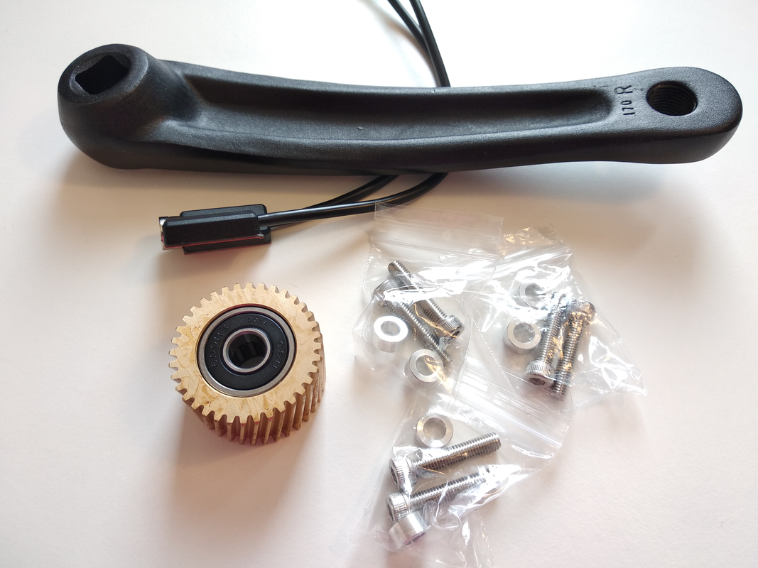
") I forgot but when I installed the motor I stripped the Suntour crank arm removing it so I did not tighten these cranks too much in case I needed to remove them again. We will give it a try in a little while, hopefully that will correct the noise issue. I guess it make sense because the crank arm is always in the same place when it makes the noise, and it is about the location where it gets the most torque.
I forgot but when I installed the motor I stripped the Suntour crank arm removing it so I did not tighten these cranks too much in case I needed to remove them again. We will give it a try in a little while, hopefully that will correct the noise issue. I guess it make sense because the crank arm is always in the same place when it makes the noise, and it is about the location where it gets the most torque.