
jbalat said:See if you can still read the LCD ? Just checking that your drivers are still working..
Yep, read the LCD3 fine.
jbalat said:See if you can still read the LCD ? Just checking that your drivers are still working..
 . As lots of people have done this successfully there’s something I’m not doing right; what can it be?
Don't know. Can you read things like the OPT or EEPROM? Try to erase, unlock, etc the STM8.aja said:I’ve made another short cable but this time using the speed sensor cable end; identical problem; this is a total waste of time
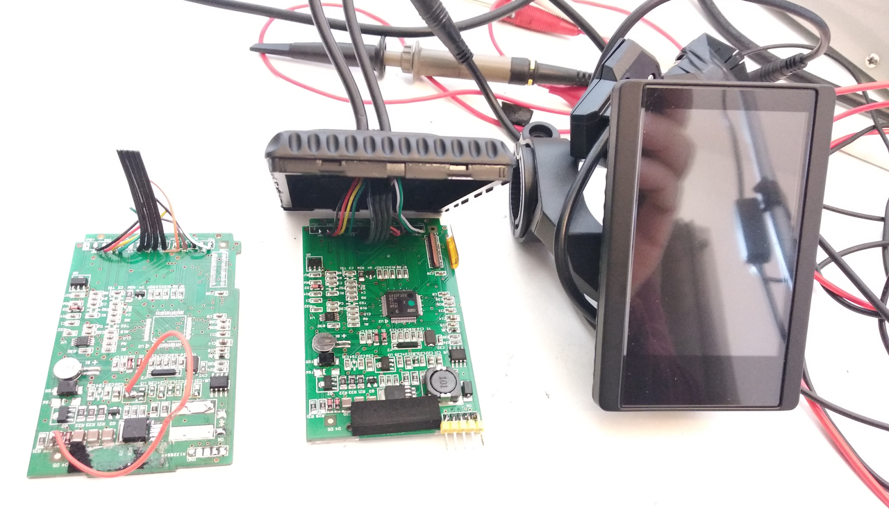
I soldered connections onto the speed sensor cable so that it could be connected to the ST LINK V2. My cable is about 10-11cm long. I also made a 9cm then cut it down to 5cm home made cable before I bastardised the speed sensor cable. 4 wires including 5V for power are connected.
I have Windows VM running.
I open up the ST Visual programmer application.
I plug in the ST LINK V2 to the USB already plugged in to the TSDZ2. A blue light shines on the ST LINK V2.
I click on the USB bar in Windows and select the ST LINK V2
I select STM8S105x6 (I have also tried the x4 variant; makes no difference).
Port: USB; Programming mode SWIM.
I then try to read the controller by pressing Read all tabs: I then get the following error:
Cannot communicate with device!
Check Swim cable connection and check all the needed pin connections on the Swim connector.
If the application code uses Swim Disable and Reset pin as output or has disabled SEIM clock divider. Try now to Switch off and on the application power supply while NRST reset pin is forced low.
The light alternates from blue to red a couple of after the error pops up then goes red.
Where am I going wrong?
How do I read OPT or EEPROM? and indeed how do I erase or unlock the STM8? Is OPT, option byte?casainho said:Don't know. Can you read things like the OPT or EEPROM? Try to erase, unlock, etc the STM8.aja said:I’ve made another short cable but this time using the speed sensor cable end; identical problem; this is a total waste of time
I soldered connections onto the speed sensor cable so that it could be connected to the ST LINK V2. My cable is about 10-11cm long. I also made a 9cm then cut it down to 5cm home made cable before I bastardised the speed sensor cable. 4 wires including 5V for power are connected.
I have Windows VM running.
I open up the ST Visual programmer application.
I plug in the ST LINK V2 to the USB already plugged in to the TSDZ2. A blue light shines on the ST LINK V2.
I click on the USB bar in Windows and select the ST LINK V2
I select STM8S105x6 (I have also tried the x4 variant; makes no difference).
Port: USB; Programming mode SWIM.
I then try to read the controller by pressing Read all tabs: I then get the following error:
Cannot communicate with device!
Check Swim cable connection and check all the needed pin connections on the Swim connector.
If the application code uses Swim Disable and Reset pin as output or has disabled SEIM clock divider. Try now to Switch off and on the application power supply while NRST reset pin is forced low.
The light alternates from blue to red a couple of after the error pops up then goes red.
Where am I going wrong?
aja said:I’ve made another short cable but this time using the speed sensor cable end; identical problem; this is a total waste of time
I soldered connections onto the speed sensor cable so that it could be connected to the ST LINK V2. My cable is about 10-11cm long. I also made a 9cm then cut it down to 5cm home made cable before I bastardised the speed sensor cable. 4 wires including 5V for power are connected.
I have Windows VM running.
I open up the ST Visual programmer application.
I plug in the ST LINK V2 to the USB already plugged in to the TSDZ2. A blue light shines on the ST LINK V2.
I click on the USB bar in Windows and select the ST LINK V2
I select STM8S105x6 (I have also tried the x4 variant; makes no difference).
Port: USB; Programming mode SWIM.
I then try to read the controller by pressing Read all tabs: I then get the following error:
Cannot communicate with device!
Check Swim cable connection and check all the needed pin connections on the Swim connector.
If the application code uses Swim Disable and Reset pin as output or has disabled SEIM clock divider. Try now to Switch off and on the application power supply while NRST reset pin is forced low.
The light alternates from blue to red a couple of after the error pops up then goes red.
Where am I going wrong?
I program with the motor controller powered on and for that, the LCD must be powered on and enable power to the motor controller........maximusdm said:To make cables even shorter I connected directly into the board! Same result. Please see picture.
I made swim on black wire pin, reset on purple, ground on LCD black wire. Please see picture.
I have the LCD cables cut out. Is this a problem?
https://imgur.com/a/jHlqWDS
https://imgur.com/a/K7M5iK9
EDit: i have no idea how to attach picture. How do you do it?
aja said:Hi,
Using a Macbook Air 2011
When you say ‘write’ I take it you mean ‘program’ as I don’t see a ‘write’ anywhere.
Did you try to read the current tab or all tabs before trying to program/write to the motor controller?
I haven’t tried to program the ST Link yet as JB suggested ensuring that it could read first; I take it that if it can’t read then it can’t write/program?
I’ve lost count of the times that I quit STVP and started it again!
Are you using STM8S105x4 as JB mentioned that x6 is now used for both screen and motor?
That is an important detail. Thank you!casainho said:I program with the motor controller powered on and for that, the LCD must be powered on and enable power to the motor controller........maximusdm said:To make cables even shorter I connected directly into the board! Same result. Please see picture.
I made swim on black wire pin, reset on purple, ground on LCD black wire. Please see picture.
I have the LCD cables cut out. Is this a problem?
https://imgur.com/a/jHlqWDS
https://imgur.com/a/K7M5iK9
EDit: i have no idea how to attach picture. How do you do it?
aja said:Can someone please help me; I've tried connecting the ST Link to the Speed sensor on the TSDZ2 to flash the firmware to the motor but whatever I do, I get the same Swim comms error; started with cables inc connectors at 9cm and cut them down to 5cm...still doesn't work; spent the whole weekend creating cables then soldering and re-soldering t different lengths; nothings worked. I do have a speed sensor cable but don't want to cut it up if I get the same result as I've followed JB's and Casainho and indeed Eco ebikes instructions but to no avail.
I've flashed the 0.14 hex file to the LCD3 without a problem.


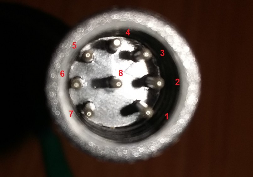
andyme said:I am not sure if this will help you, but i want to relate 2 things re. the motor flash cable with 6 pin connector .
pls refer to the pic. this is what the connections should be looking from the front. also: you can make your own female plug by using e.g. short pieces of tiny brass tubes that will fit over the motor connector pins. this way you do not have to use sensor cables etc... i tried to use a speed sensor cable from another bike..there were only 2 wires in it...these tubes are used in modelling, RC toys etc
the length of my cable is about 15 cm, it works perfectly well. i am using a tube with 0,9 mm inner diameter and 0,2mm wall thickness, 0,8mm would be even better if available connector made from tube.jpegtsdz2flashconnector.png
andyme said:i can only say that i have the motor connected to the battery, but i did not turn the lcd on...on the other hand: it will not harm either...
I am more and more interested on this type of DIY. I would prefer to go with an already existing LCD for ebikes but seems very hard to make the LCD working when we have no datasheet of it -- I also saw a lot of forum messages of people with this type of problems for cheap LCDs to Arduino, where chinese guys sell them saying they use a specific LCD driver but in fact use some different....feketehegyi said:fyi, I've made a TSDZ2 Display from scratch
[youtube]yoJl_CpBqrY[/youtube]
casainho said:I am more and more interested on this type of DIY. I would prefer to go with an already existing LCD for ebikes but seems very hard to make the LCD working when we have no datasheet of it -- I also saw a lot of forum messages of people with this type of problems for cheap LCDs to Arduino, where chinese guys sell them saying they use a specific LCD driver but in fact use some different....
I had one idea: why not recycle ours TSDZ2 VLCD6 and use the enclose to put inside the Arduino + the LCD??
I think a color LCD of 3.2 inches takes the area of the original LCD of VLCD6. And even we could reuse the original UP, DOWN and POWER buttons of VLCD6!!
What I think we need (this is the hardware of Bafang Color LCDs):
- 1x Arduino (I would go with 32bits STM32 Bluepill board, because is small, cheap, powerful and we can use the same flash/development tools for TSDZ2)
- 1x 3.2 inches color LCD (there are some versions already of IPS TFT that should give a better reading outside light) -- connection by SPI
- 1x Arduino RTC (real time clock, so the system can have tie/clock) -- connection by SPI
- 1x 60V to 5V DC-DC (to power the system)
- 1x some switch to power on/of the motor controller
Optional:
- 1x Bluetooth module
- 1x other hardware for bicycle sensors
Doing DIY is not good as most users will simple not do it. The probability for errors are much higher...
What is your plan??
My Arduino and SPI TFT setup is a proof of concept only. A mobile phone connected to TSDZ2 via bluetooth is the best display imho.casainho said:What is your plan??