• Hello ES! We could use some help to get us past the finish line on building the new knowledgebase for the forum.
    Can you donate? Please see our fundraising page. Thank you!

Nissan Leaf motor at 60V, 1/6 the power?

I'm not sure what is overmodulation factor and why it could be bad to set it over 1.15, but there is huge difference in power and RPM in my set up.
I tried setting at 1.0, 1.15 and 1.30. New power record was at 1.3.
Bump!
Is someone can share more details about the overmodulation factor I'm talking about post 121?
Thanks
 
Last edited:
I've found this useful information about overmodulation. 6.06 Overmodulation Guide
Still, it's really skateboard related and I'm far from this with ''huge'' 360V motor and ''huge'' 60V battery.
So, I'm not sure what to learn about this considering my use case.
 
[ Upon seeing this thread thought will familiarize with overmodulation (in general, not VESC specific), so far i have been into basic FOC only ]

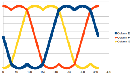
Following would be the per phase voltage waveforms without overmodulation,
noovermod_ph.png

And phase to phase,
noovermod_ph_ph.png

With overmodulation factor of 1.15, per phase would become as follows,
overmod15_ph.png

while the phase to phase as below,
overmod15_ph_ph.png

And with overmodulation factor 1.3, per phase & phase to phase would be as follows,
overmod30_ph.png

overmod30_ph_ph.png

Per your graphs variation in duty cycle is less with increasing modulation. I am on a shaky ground here - wondering whether Leaf motor is a trapezoidal back emf type
 
Thanks for your input on the subject.
I have to digest all this as I'm not sure to fully understand.
Especially when I look another time a my VESC graph of the Leaf motor with ovemodulation set at 1.15 and 1.30
 
I think I may have gotten a little lost, are you listing power input figures and increasing those while also increasing the regen motor load. I'm just wondering because you should be careful as you can easily increase power input numbers without increasing motor power output with the wrong settings. Ideally you should be looking at both input and output power to ensure your efficiency is reasonable and you aren't for instance increasing input power by 1kw but only gaining 100w of output power.
 
are you listing power input figures and increasing those while also increasing the regen motor load.
I'm listing power input and I'm playing with regen load quite a lot to test many things.
Still, generally, for a same regen load (let say 1000pA on ME1507) if I increase input power, rpm go up (so power).

I would like to do a 10 kW efficiency test for, let say, one hour with different parameters.
But that will be a Dyno with a Leaf motor fitting a Leaf motor because at the moment, the poor ME1507 motor don't like to brake the Leaf motor at 1000pA for more than few seconds at slow 1000 ish RPM.
 
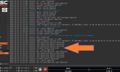
Ok, I effectively have problem with the MT6816 encoder.
It look like VESC detect something as it seem to detect encoder ratio (2147,5).
Two thing I'm not sure:

1-Encoder connections. MOSI = V+. See 3e pic. There is a MOSI on the MT6816. Is I have to connect it to V+ or no?
I've connect VCC to V+, CSN to CN... right?

2-How to set encoder on VESC? Simply select MT6816 in General Motor setting/sensor, select encoder in FOC Sensor mode and run Detect encoder... or there is a specific way?

Encoder-1.JPG
Encoder-2.JPG

1761235027390.png
 
I do not know how to connect that encoder to your VESC, but you can check the VESC for Bafang M600 motor controller schematic with that encoder and see how it is connected to MCU, maybe you need to connect it the same way.


It also looks like that encoder has multiple modes depending on how you connect it (you can check those modes in the encoder datasheet). But if you connected the encoder properly to set the encoder in the VESC Tool after connecting the controller go to "General"-->"Sensors" and in the "Sensor Port Mode" select your encoder, then click the "write the motor" button in the right side menu. Then go to "FOC"-->"General" and select the mode with encoder in the "Sensor Mode", then click the "write the motor" button in the right side menu. Then go to "FOC"-->"Encoder" and follow this sequence VESC for Bafang M560

After this the motor in encoder mode might start working. It also looks like the "Encoder Ratio" is equal to amount of pole pairs or half amount of the rotor magnets. So you also can try to count the amount of magnets on your rotor, divide it by half and put this number in the "Encoder Ratio". Do not forget to press "write the motor" button in the right side menu if you want your changes to be applied to the controller.
 
Last edited:
You're far better off getting an ABZ/ABi encoder. The mt6816 is good, I've used it a lot but the spi encoders aren't being actively developed and tested on VESC whereas the ABi ones are.

If you continue with the SPI one you'll need to select it on the encoder page before doing the setup. The ratio is the number of pole pairs so 2047.5 isn't a meaningful ratio.
 
Haha! Do you know main reason why I choose MT6816?
I'm open to suggestion for best option for ABI encoder 😆
View attachment 379644
Sorry... They come in ABi and SPI versions... The mt6816 ABi version is the one I use by default for everything... My bad not saying...

Mt6701 is also good.

You can hypothetically reprogram yours but that's a bit of a mission...
 
The mt6816 ABi version is the one I use by default for everything...Mt6701 is also good.
How to see the difference between?
I found MT6701 and MT6816 encoder for sale, but how to see/know if it's an ABI model?
 
Read this discussion


After some research we come to conclusion this rotary encoder has only one flavor and it has multiple modes included (and there is no ABI mode), and which mode it works in depends on how you connect it to MCU and how the MCU processes it (firmware algorithm on the MCU side). It looks like you can program some parameters of the encoder EEPROM (stuff like resolution, SPI 3 or 4 wires connection mode, pole pairs) and you have to ask the manufacturer sales division about how to do it (that's what the datasheet says).

There is no ABI mode, except ABI is misrepresentation of the standard ABZ term. But the encoder has ABZ mode along with other modes, there is no special version of the chip and no special programming of the encoder. Just appropriate electrical connection dedicated for the mode you want and proper firmware algorithm on the MCU side to read the data from the chip.

1761705248383.png

The only thing I can think of is maybe VESC firmware in ABI mode needs stuff like specific resoludion and maybe pole pairs set in the rotary encoder EEPROM to work with it properly and default or random parameters in the encoder settigs messes things up in the VESC firmware (because of VESC firmware probably can not be adopted to it the easy way or something). Which is again you have to ask the sales team of the encoder manufacturer how to set these parameters. But VESC does not tell anything about those parameters anyway so you have no idea what those parameters are even if you know how to set those parameters on the the MT6816 chip.

1761705984912.png
 
Last edited:
How to see the difference between?
I found MT6701 and MT6816 encoder for sale, but how to see/know if it's an ABI model?
77638.png

The acd version is what you want or ace. The mt6701 i think comes with abi as default.

ABi = ABz. There's no difference. i stands for index, z stands for zero.
 
That's interesting. It looks like there is a chance your MT6816 chip might have correct settings.

I did not know this and just purchased AKD-R version of the chip on lcsc.com for the VESC for Bafang M600 controller because of this is how the Luna encoder marked (It is marked 6816 134 and it matches to the AKD-R version and STD-R version according to the pictures on the lcsc.com). AKD-R is more expensive than STD-R so I decided to use AKD-R (thinking the expensive one is better), and it works just fine on VESC for Bafang M600 controller. While it works in 4 wire SPI mode on the VESC for Bafang m600 controller the table mxleming posted mentions different mode for AKD version.

So it certainly can work in multiple modes no problem and there is a chance your encoder might have the correct settings for the mode you want. I did not find information about the MT6816 chip markings, maybe mxleming has that information also and can post it here so you can check the marks on your chip to figure out what the settings exactly are and if they match to what you need.

1761753848684.png

If mxlemming does not have markings info you can check the markings pictures on lcsc.com browsing through the items and see what exactly you have.


But even if your chip marked STD (4 Wire SPI mode) like on the picture with PCB you posted above you still do not know what the settings are for other modes and those settings might work fine with VESC in SPI mode. There is only one way to find out.

By the way, the rotary encoder on Bafang M560RS motor controller is marked 6816 ACV 502. I do not see such markings on lcsc.com or in the table mxleming posted. But it looks like that thing works in ABZ mode

 
Last edited:
you should be careful as you can easily increase power input numbers without increasing motor power output with the wrong settings.
I was still doubt that overmodulation wasn't giving anything, so I tried some other tests.
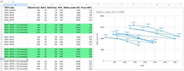
Here is many nice numbers from my tests. Clearly, overmodulation give more rpm, but 1.25 vs 1.15 mainly give more motor loss (9% more power only give 3-4% more rpm).
Sadly, I stuck to have a nice graph with 5 lines for each different setting.
If someone can create a nice graph with those data, please feel free.
https://docs.google.com/spreadsheets/d/1l55PA_GWMiyrY8HDAXg9dPJcLT-LUvorUsZrS-LRVoY/edit?gid=0#gid=0

1761837861841.png
 
Based on data you can see above, passing from 300A setting to 400A setting increase power by around 15%.
This is despite the pA are only 226A to 276A max.

My question: how much power can I expect if I purchase a VESC Maxim able to 600A?
Another 15-20% or not?
 
Based on data you can see above, passing from 300A setting to 400A setting increase power by around 15%.
This is despite the pA are only 226A to 276A max.

My question: how much power can I expect if I purchase a VESC Maxim able to 600A?
Another 15-20% or not?
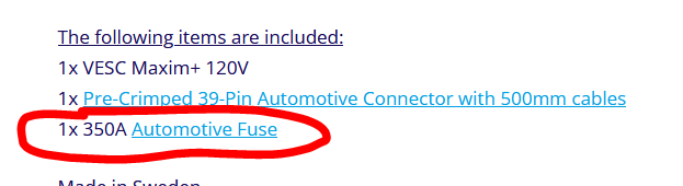
You can check the datasheets they posted. If you mean the VESC Maxim+ 120V 660A (I did not find 600A) it is capable no more than 350-370A (400A is the maximum fuse amperage they allow for this controller). 660A in the controller name is just to demonstrate the safety margin (basically marketing). The actual amperage is below 400A. And most likely below 350A (like 300-320A or so) because of this is the fuse they supply this controller with.

To calculate the maximum power just multiply the maximum amperage on the battery voltage.

Let's say you use 120V battery and maximum amperage is 300A. So you can expect 120V x 300A = 36000W of power maximum.

1763074638124.png

1763073647428.png
 
Last edited:
And most likely below 350A (like 300-320A or so) because of this is the fuse they supply this controller with.
Well, this fuse can pass over 900A for 10 sec and over 600A for a minute based on the data sheet.

I'm looking at more than basic math calculation as I actually have Nissan Leaf motor data at 60V.
I mean, I adjust max pA to 300 and it only reach 226A (175 batt Amps). Then, only 276A (206 batt Amps) when set at 400A, so how much I can expect at 600A?
Is it linear?
 
Well, this fuse can pass over 900A for 10 sec and over 600A for a minute based on the data sheet.

I'm looking at more than basic math calculation as I actually have Nissan Leaf motor data at 60V.
I mean, I adjust max pA to 300 and it only reach 226A (175 batt Amps). Then, only 276A (206 batt Amps) when set at 400A, so how much I can expect at 600A?
Is it linear?
The relation between phase amp and battery amp is complex and not deterministic without knowing the motor and operating point.

As you've seen with field weakening and MTPA, there are many combinations of id and iq that work with varying success. These result in wide ranges of efficiency.

The equation is
P =3/2*(Vd*id +vq*iq) =Vbat*ibat. The modulus (hypotenuse) of Vd and Vq has a maximum of Vbat/sqrt3.

Therefore in the perfect case is a resistance and inductance free motor you get ibat = sqrt3/2 x iphase and any imperfection will make it lower than this.

There's of course an approximately linear relationship with duty cycle as well... Ibat=k*iphase*duty

You can be sure that you never have Vd and vq in exact proportion with the id and iq counterparts, therefore power factor is always substantially below 1 and the battery amps can only ever approach the theoretical perfect limit

This is why it's very normal to fuse a 600 phase amp controller with a fuse much less than 600A, as well as the fuse surge capacity you just mentioned. This isn't a controller limitation, this is the reality of physics. You can have arbitrarily bigger phase current than battery current but you can never get as many battery amps as phase amps, basically because of the motor inductance and how math works.

Maxim 120 is realistically 1.5x the current capacity of the 75300. Maxim+perhaps 2.5x. whether you can utilize that in a meaningful way with the limited battery voltage... No idea... Probably not?
 
Well, this fuse can pass over 900A for 10 sec and over 600A for a minute based on the data sheet.

I'm looking at more than basic math calculation as I actually have Nissan Leaf motor data at 60V.
I mean, I adjust max pA to 300 and it only reach 226A (175 batt Amps). Then, only 276A (206 batt Amps) when set at 400A, so how much I can expect at 600A?
Is it linear?
Additionally, try the motor simulator. It takes some getting used to, Benjamin has not made it particulary intuitive, but if you set correct parameters in the foc and additional info tab and use the Vb + FW option you can plot various maximum powers and so on. It's very easy to drown yourself in accidental errors but it does work...
 
Last edited:
whether you can utilize that in a meaningful way with the limited battery voltage... No idea... Probably not?
Why not?
2 time 10 kW at propeller shaft will move some water, then our solar Catamaran quite well.

Thanks for your input. Good info as always.
 
Why not?
2 time 10 kW at propeller shaft will move some water, then our solar Catamaran quite well.

Thanks for your input. Good info as always.
Ultimately you're limited in power by how much current you can push in against the inductance
iphase=Vphase/(jwL)

With vphase =vbat/sqrt3, w=erpm*2π/60,

When w is small you can push any amount of current, limited only by resistance, but as you start to spin there's a fundamental limit from inductance.

Also, beware of just looking for higher power reading on the VESC tool. You want to get the highest output power for your input power. VESC only shows input power. So optimised for rpm x torque.
 
Back
Top