Not Ebike, but an UGV project with a Chinese ESC, help for determining a few plugs/wires needed

eMachine

100 µW
Joined
Aug 13, 2024
Messages
7
Location
Finland
Hello everybody,
Edit, the circuitboard is kh324-fs-1
I researched this for a very long time and the best reponse I found a few reddit replies saying that "hey you should ask it on endless-sphere", so here I am.
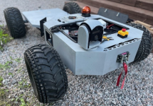
I am a roboticist, usually I use canbus and high level controllers, but this time I need to use ESC's I have to complete a business case prototype UGV for a few surface maintenance utilities:
1723571593888.png

I already figured the most of plugs/wires. I programmed a remote teleoperation software to connect to UGV using 4g, I can change direction, change speed and do basics using a remote base station and handheld computer (asus rog ally)
The ESC is awesome for moving this 250 kg UGV with 48V, no complaints.

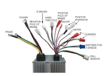
All I want is to figure out what are the rest of wires. The documentation shows plugs but colors are totally different:
1723571854565.png

I'm left with a few plugs:
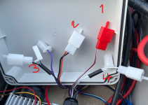
1723572044869.png
1-Can I assume, red plug with one dualcolor wire is the "Positive pole of brake"? How is this wired? I don't have a mechanical lever. Is it for brake lights or actually regen-like motor brake?
2-Plug with red and black wire next to red plug is the "Negative pole of brake"? How is this wired? I don't have a mechanical lever.Is it for brake lights or actually regen-like motor brake?
3-No idea. There is a black plastic tube binds these two.
4-Two white wired plugs are "positive inversion"? This reverses the motor I assume.

I'm really sorry if these questions sound too dumb, I have never ever built anything with ESCs in my life, just used high level programmable motor controllers. I'd really appreciate if you could help me determine these wires, especially help me plug nr1 and 2 (or either) wires to correct place.
 
Last edited:
I'll answer as best as I can, but please take it with a grain of salt, as these chinese-made generic controllers have a lot of similar connecters, but potentially not all following the same color scheme.

1. Red connector with only a single wire, this is commonly connected to B+ to turn the controller on.
2. Occasionally the "brake" when connected to group, shuts off motor input. For example, if you use this switch on and ebike's brake lever, it would prevent the motor from spinning while the brake is held.
3. Also not sure, sorry
4. Likely these are self-learning wires. When first connecting a controller and motor, you would connect the two white wires together and they will slowly spin up your motor. If it is spinning in the correct direction, you disconnect the two white wires and turn off the controller. If it is spinning in the wrong direction, you disconnect the two white wires, and reconnect the two white wires, and the motor should then spin in the desired direction.

It may be helpful to indicate what wires you have already connected and used. Also it's unclear from your description: have you already gotten this controller working, and you just want to use up the rest of your connectors?
Hi, thank you!

From below screenshot, I used:
1-phase
2-power
3-R-driver (reverse, my microcontroller signals this)
4-Hand throttle (only green and black wires to my microcontroller, red wire not used)
5-on/off
6-3 speed shifter
7-hall wires

Controller already works and I want to figure out if there is really a brake function or not in this ESC. Thus instead of using drumbrakes with a hydraulic actuator, I'd love to manage brake with software and ESC

1723574851086.png

Edit: I also found this online, looks very similar:
1723575003221.png
 
Last edited:
Positive Pole of brake, could also be a high brake Signal (+12V) to shut off Motor or activate Regen braking.
Negativ Pole..., could also be low brake Signal (0V or ground) to cut off motor...
 
I think guardian is for the alarm system
Positive inverter it sounds like reverse ?? How much voltage is coming out of the brake connectors can you light a a 12 volt automotive light with them or will it blow it ? Sacrifice.
 
Last edited:
I would chop off all the red connectors and the negative brake. Keep the 3 speed if you need it, but i'm sure you could operate that remotely as well if you have a free channel. I'm guessing you'll want to retain the reverse function, but now might be a good time to explain what functions you require. you're better off managing braking separate from the controller.
 
I would chop off all the red connectors and the negative brake. Keep the 3 speed if you need it, but i'm sure you could operate that remotely as well if you have a free channel. I'm guessing you'll want to retain the reverse function, but now might be a good time to explain what functions you require. you're better off managing braking separate from the controller.
Hello,

is there any specific reason why to avoid ESC brake if it has the function? Most ESC's seem to execute brake functions very well including my daughter's escooter. I kept the 3 speed and tested on a large field, other than that using the ugv with the lowest speed. Reverse function is also actively used.

I would like to really have either motor shut off or motor brake.
 
No reason; if that’s a requirement, then maybe it’s a good time to describe your drive system, motor(s), gearing/transmission, etc., to see what is feasible. Are you saying you’ll be using one or more scooter motors?
I have two brushless motors connected to two separate ESC’s. Each motor is installed to differential axle, axles have gear reduction and also 2 speed transmission.

Both ESC’s get pwm signal at the same time. I would like to have a motor brake at least for one of the axles.

Looks like the ESC i have high level motor cut off and low level cut off. I have to disassemble the esc and test some terminals to look for ESC brakes; common name for this function seems to be EBS in China.

Edit:
Figured out by testing. I contacted the positive pole brake to positive of the battery, cuts off the motor.

I shorted negative pole of the brake, same thing happened.
 
Last edited:
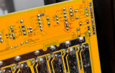
I opened the ESC and pulled the pcb out. A yellow pcb with model marking kh324-fs-1.
Most functions have markings.
I found EBS- and EBS+:
1723632905366.png
Orange wire (from negative pole of brake plug) is soldered to two slots on EBS-
Cherry/white wire (from positive pole of brake plug) is soldered to EBS+
 
RRemember when using a motor for Regen it talks very hard in the opposite direction and we'll loosen nuts and bolts if the motor isn't totally firmly connected to a strong base over protection for a motor used for regen is smart.
 
RRemember when using a motor for Regen it talks very hard in the opposite direction and we'll loosen nuts and bolts if the motor isn't totally firmly connected to a strong base over protection for a motor used for regen is smart.
Motor is totally firmly connected, previously tested with oDrive controllers and brake resistors. Not a single problem after days of tests. Base is strong and mig welded.
 
What kind of battery do you run in how many watts of Regen does that motor kick in ? How heavy is the driver that would make a difference with the regen Through or around the BMS ?
 
Last edited:
Back
Top