one more try at sorting out this flaky motor issue ...

woofnbike

10 W
Joined
Aug 2, 2020
Messages
87
it's been over a year since i tried getting this scooter going but i am going to give it one last go. it's got a bafang motor, one of the so-called jump ones that is hall free, connected to this: 24V/36V 350W 6MOSFET Brushless Motor Controller with the good ol' 810 display. at one point, the motor ran too fast but that issue went away -- don't know how -- only to be replaced with one wherein the motor runs but only at a level too low to even move the trike. the mode lights on the display work but don't change anything. the throttle works to the degree that it ramps up to its current max. any thoughts on what i might try?

oh, and i did try changing the connection order of the blue/green/yellow wires from controller to motor, to no effect.
PXL_20240927_203002209.jpg
 

Attachments

  • PXL_20240927_203057878.jpg
    PXL_20240927_203057878.jpg
    3.3 MB · Views: 16
  • PXL_20240927_203002209.jpg
    PXL_20240927_203002209.jpg
    3.7 MB · Views: 16
Ya those pics are good enough to see the label on the controller or what’s going on with the wiring, so can’t help much. Do you any info from the vendor in the controller?
You shouldn’t have to worry about wiring order if you’re running sensorless. Just plug it in and give the wheel a nudge in the right direction when you apply throttle and it should spin.
Good luck!
 
sorry. let me see if i can do better. a throttle i once had did not ramp up; was broken so it went either all on or all off. the one i have now works as a throttle should, turning the wheel faster; it's just that the top speed is very low and not enough to move the trike forward. hope that helps. thanks for weighing in!
 
Do you have a multimeter you can use to check the signal voltage from your throttle? Most controllers are programmed to map 0-100% throttle against something like 0.8 to 4.0 volts, corresponding to the output range of a Hall sensor powered with +5V.

If you've swapped a potentiometer throttle for a Hall throttle, or you've switched to a very different range pot, then you might be proportioning (say) 0-5% power against the output of the throttle.
 
i do have a multimeter but how to use it to accomplish the checking you suggest -- i'm clueless. could you offer some guidance?
 
meanwhile, here's a few pix of how i have things connected, most of it half-baked until i get things sorted out.

first one is controller to motor.
second, with the junction thing, is the throttle
third one is the display.

also: i once wrote the seller about the display / controller combo (they were sold together) and he wrote back:

Power assisted strength control: The icon area for the power strength control area and display area, power-on the default power strength for LOW power strength control line output voltage 2V, each press the next key power signal will change once, the first time to press the power strength indicator light will jump from LOW to MED at this time voltage output 3V, The second time to press the power intensity indicator light will jump from MED to HIGH voltage output 4V, the third time to press the power intensity lamp back to LOW voltage back to 2V.

could my problem be related to the fact that my scooter isn't a bike so it doesn't use PAS?
 

Attachments

  • PXL_20240930_215134121.jpg
    PXL_20240930_215134121.jpg
    2.2 MB · Views: 11
  • PXL_20240930_214934333.jpg
    PXL_20240930_214934333.jpg
    2.2 MB · Views: 11
  • PXL_20240930_214747635.jpg
    PXL_20240930_214747635.jpg
    2.1 MB · Views: 12
Last edited:
It looks like “strength control” may just adjust the max throttle voltage used by the controller to determine the speed. 4v would be the about max throttle voltage of a normal throttle, so setting it to high, would give you full throttle.

You should still check your throttle output voltage though. Tommycat’s guide is an excellent guide for all things throttle, including checking voltages.
 
well, here's what i came up with.

1/ at the junction of throttle to controller, with probes connected red to red and black to black: .01 at zero throttle and .24 at full throttle. (with display mode changed to high: .01 and .50)

2/ with probes connected black to black and green to the meter's red: .01v at zero throttle and .25 - .30 at full. (with mode changed to high: .01 and .37)

that's what i got. whether i did the testing right, i'm not sure. if i did, the results don't look good, do they?
 
The red to black voltage should be about 4.3 volts, Green to black will vary from about 1V to 4V when you turn the throttle.

Let's find out if the meter is working right, WHat do you see when you put the meter on the battery?
 
The red to black voltage should be about 4.3 volts
… and should not vary with throttle twist.

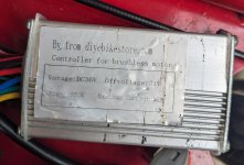
A link to your new throttle, and a picture of your controller’s sticker may be helpful.

Readings as you’ve indicated shouldn’t even have the voltage to start the motor.
 
here's some pix.

1/ controller
2/ throttle connection with multicolor connector and black display conector
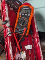
3/ black to green with output, throttle at max
4/ close up of black to green
5/ red to black with output, throttle at max
6/ close up of red to black
7/ scenic shot.

thoughts? suggestions?

PXL_20241001_170040392.jpgPXL_20240930_214934333.jpgPXL_20241001_173304622.jpgPXL_20241001_173310675.jpgPXL_20241001_173444085.jpgPXL_20241001_173450898.jpgPXL_20241001_173558186.jpg
 
okay, the knucklehead is back.

1/ black to green, 5.9v. throttle at max. resting state was 1.8
2/ red to black, 5.3. resting state was 1.6

where to next? thanks. and thanks for your patience.
 

Attachments

  • PXL_20241001_183313708.jpg
    PXL_20241001_183313708.jpg
    2.4 MB · Views: 8
  • PXL_20241001_183204587.jpg
    PXL_20241001_183204587.jpg
    2.4 MB · Views: 7
Okay, first principles: Red is (should be) +5V nominal. Black is (should be) GND, zero V. Green should be a sweep of some kind from the low end of that range to the high end of that range as throttle is applied (specific voltages depending on the type of throttle and the source voltage).

If that's not the arrangement you have, then it's not correct.
 
Remove the throttle wiring from the connector.
Measure the voltage coming from the controller with throttle removed, RED and BLACK wire. Does it come back to a true 5 vdc.

To me your latest readings indicate a millivolt reading. (Very low)

BTW, thank you for the pictures, link, and prompt responses to questions/suggestions! Much appreciated. :)
 
not 5 vdc but pretty close, right?
 

Attachments

  • PXL_20241001_204444676.jpg
    PXL_20241001_204444676.jpg
    2.5 MB · Views: 6
not 5 vdc but pretty close, right?
Definitely in the correct range and a bit of encouragement. (y)
Does this voltage value increase when you put the “mode” in “high”? If so, make all your throttle voltage tests at this value.

So as the voltage input to the throttle appears to be shorting out with the throttle connected.
It would appear to me that the throttle is bad. But I would do a bench test (see the throttle thread) on it just to double check.
Fully disconnected, apply a 5vdc source to the RED and BLACK wires. A 5vdc wall wort or USB or cell phone charger works well for me. Even using 3, 1.5 volt batteries in series to provide 4.5 vdc would work as well. Quickly see if your voltage drops when hooked up. If so, that’s it game over. If not, check the output when powered, looking for the output values mentioned earlier.

Link for your throttle replacement to verify correct throttle type and wiring?

Also looking at THE THREAD.
You could check for controller output if desired by supplying a 3vdc cell battery, positive to the GREEN controller signal wire. With the negative side connected to the controller BLACK wire. Expect 1/2 to 3/4 speed. You may have to bump it off and on quickly to jump the throttle low voltage safety…

op46I6T.jpg

ignore the 2vdc input as stated… my battery was low. Controller supply voltage is left disconnected.

Looking forward to your throttle bench tests.
 
Last edited:
well, when i hook it up, it goes to 4.27 V and stays there until i unhook and then it drops.

you wrote: "if not, check the output when powered, looking for the output values mentioned earlier." by that do you mean hook the throttle back up and check voltage using the wall wort per the throttle testing guide? i think so. so i'll do that in a minute, unless i pass out from testing-overload exhaustion first.

the throttle i have can be seen in that ebay link: 24V/36V 350W 6MOSFET ebike Electric Bicycle Brushless Motor Controller with LED | eBay. were you looking for something in addition to that?

mode hi or lo has made no difference in voltage value.

i'll have to see if i can dig up one of those 3v button batteries somewhere.

thanks for all your help!
 

Attachments

  • PXL_20241001_222521546.jpg
    PXL_20241001_222521546.jpg
    2.6 MB · Views: 3
by that do you mean hook the throttle back up and check voltage using the wall wort per the throttle testing guide?
Yes.
Surprised that the bench supply voltage is holding. That’s why we double check with different testing.

Will look at the link, and thanks for the supply voltage info.
 
in the huh, go-figure dept, hooking the green signal wire back into the equation produced ... nothing. the meter showed nothing to start with and turning the throttle produced nothing as well. i triple checked my wire connections -- ground to the black probe, green to the red probe -- and the red wire running straight through alone -- and everything looked good to me but, at the age of 70, ya never know, so i'll give it another check or two later. i am perplexed, but at least, in a certain light, nothing might be considered something.
 
in the huh, go-figure dept, hooking the green signal wire back into the equation produced ... nothing.

Well, it won't have any voltage on it unless +5V and GND are attached to the throttle, and it won't vary unless the throttle is operated.

The signal wire to the controller won't ever show a voltage; it's only listening for one from the throttle.
 
Sorry if we got off track, let me clarify just in case I didn't follow you correctly.

When "bench" testing the throttle, you do all voltage readings with it separated from the controller. I.G. You don't have to reconnect the signal wire to the controller in order to check for a variable throttle voltage when it's twisted. You just check for voltage right at the end of the green wire with it not connected to anything whist using a separate power source connected to the black and red wires, observing polarity.

But if your throttle didn't drag down or short out the provided supply voltage as stated earlier. I have a mind to think that perhaps we may just be looking at a bad throttle connection or connector.

Easy way to check, would be to not use that connector block, and just twist the bare wire ends together like they were in the connector. Being careful not to let them touch each other. And again, test the voltages as you have done previously. Being careful of the motor starting as always...

Hang in there!

I'm sorry, but in the link for your kit you provided twice, I cannot find any reference to a throttle. :confused:
 
Back
Top