

-
Hello ES! We could use some help to get us past the finish line on building the new knowledgebase for the forum.
Can you donate? Please see our fundraising page. Thank you!
You are using an out of date browser. It may not display this or other websites correctly.
You should upgrade or use an alternative browser.
You should upgrade or use an alternative browser.
Science, Physics, Math, & Myth
- Thread starter Kingfish
- Start date


Arlo,Arlo1 said:Miles the spread sheet lost the weight of the leaf motor its 123 lbs.
I will try to get some no load current later today.
Unless something happened with your copy of the spreadsheet, it's in there as 55.8kg :wink:
Ok. Thanks! That would be great.

windtrader
⚡ Regular
Can someone add the figures for the Revolt RV-120 or RV-100 motor?
What about the Astro 3220?
What about the Astro 3220?
When I hover my cursor over the ### it shows it... Why is there a ### in place of the weight?Miles said:Arlo,Arlo1 said:Miles the spread sheet lost the weight of the leaf motor its 123 lbs.
I will try to get some no load current later today.
Unless something happened with your copy of the spreadsheet, it's in there as 55.8kg :wink:
You get it when the figure (with req. no. of decimal places) won't fit in the column width. It would be odd if this was system dependent..... You're using the Excel version?Arlo1 said:When I hover my cursor over the ### it shows it... Why is there a ### in place of the weight?

rscamp
⚡ Regular
Punx0r said:Take a look at Justin_le's post above on Dec 19th. The first chart shows a fast and slow wind motor on the same controller and current limit, with the slow wind having about a 10% torque advantage upto ~18kph, then a serious disadvantage after that.
The second chart shows the effect of reducing the controller and wiring resistance on the controller for the fast wind (but keeping the same current limit), which removes this low-speed torque advantage, leaving both motors equal upto @18kph and the fast wind having the advantage after that.
Thanks. I did look at that but didn't see the battery currents. I must admit I assumed there wasn't current limiting in the example.
Duplicating Justin's chart, I get the same curves with the following data if the motor is loaded for only 5km/h speed and lo and behold! Cool...
Attachments

Interesting because that's very slow indeed.
John, as to why the fast wind motor makes less and less torque compared to the slow wind motor as speed increases, my assumption was that the fast wind motor just isn't drawing all the current that's available, whereas the low speed wind is still bumping up against the current limit. I'd speculate this was to do with the higher resistance/impedance of the motor winding and possibly it's interaction with the source (controller/cable) impedance. I say speculate because I'm unsure whether we're dealing with AC or DC: The motor "sees" DC, but the controller pumps out AC. If we're talking AC then we possibly have a situation of load-matching determining power transfer to the motor. I agree it would be great to have a proper answer from someone who knows
John, as to why the fast wind motor makes less and less torque compared to the slow wind motor as speed increases, my assumption was that the fast wind motor just isn't drawing all the current that's available, whereas the low speed wind is still bumping up against the current limit. I'd speculate this was to do with the higher resistance/impedance of the motor winding and possibly it's interaction with the source (controller/cable) impedance. I say speculate because I'm unsure whether we're dealing with AC or DC: The motor "sees" DC, but the controller pumps out AC. If we're talking AC then we possibly have a situation of load-matching determining power transfer to the motor. I agree it would be great to have a proper answer from someone who knows

sn0wchyld
🚴♂️ Mega poster
Punx0r said:Interesting because that's very slow indeed.
John, as to why the fast wind motor makes less and less torque compared to the slow wind motor as speed increases, my assumption was that the fast wind motor just isn't drawing all the current that's available, whereas the low speed wind is still bumping up against the current limit. I'd speculate this was to do with the higher resistance/impedance of the motor winding and possibly it's interaction with the source (controller/cable) impedance. I say speculate because I'm unsure whether we're dealing with AC or DC: The motor "sees" DC, but the controller pumps out AC. If we're talking AC then we possibly have a situation of load-matching determining power transfer to the motor. I agree it would be great to have a proper answer from someone who knows
all to do with one thing - back emf (electro motive force)
as the motor spins, it effectively acts as a generator. The faster it spins, the higher the voltage it generates. so when your controller tries to apply your battery's voltage across a phase (in order to make current flow and thus generate torque), its hindered by the voltage being generated by the motor. So if your motor is generating 9v, and your battery pack is 20v, at WOT your controller can only apply 20-9=11v across a phase, and thus provide less current to the motor ( I=(Vbattery-Vbackemf)/R ) compared to a motor at 0rpm (where Vbackemf would = 0 ), and thus less torque.
The 'slow' wind motor generates a higher back EMF for a given rpm, hence why its torque drops faster than the 'fast' winding.
There's more to it than that, but thats the 'simple' answer.
To answer other points...
the motor only ever sees AC, though really its AC made up of lots of little 'squirts' of DC...
Hmm. In previous discussion it was concluded that due to the inductance of the motor winding the PWM would appear to the motor as DC with a slight ripple?
Regarding the BEMF explanation, can we demonstrate it with the motors Justin used in his last example? Namely, the H3525 and the H3540 if we know phase resistance and phase current and rotational speed? I imagine you are correct but would love to see it laid out.
Also, why is the controller/wiring resistance significant (the change from 50 to 10mOhm)? Or despite this being small, is it actually a significant fraction of the phase resistance, which being in series exacerbates the BEMF issue you already described?
Regarding the BEMF explanation, can we demonstrate it with the motors Justin used in his last example? Namely, the H3525 and the H3540 if we know phase resistance and phase current and rotational speed? I imagine you are correct but would love to see it laid out.
Also, why is the controller/wiring resistance significant (the change from 50 to 10mOhm)? Or despite this being small, is it actually a significant fraction of the phase resistance, which being in series exacerbates the BEMF issue you already described?
John in CR
📜 Mega legend
I was referring to what happens at low rpm (below the slow wind motor's peak power), which is the only place the slow wind motor shows any advantage using the same controller and battery, ie someone buys a slow wind motor and changes nothing else. Below that point both draw the same current from the battery, which is limited by the controller, not BEMF. After playing around with the simulator some more and having Justin's words sink in better, that small advantage all but disappears as more capable controllers are used, while still maintaining the same system outside of the motor for both motors. Phase current is higher for the faster wound motor, so for identical performance at low speed, the faster motor still would need larger gauge phase wires, but even with stock wiring the difference becomes negligible with a better controller.
The bottom line is that the only performance difference at low speeds is related to resistance from the winding termination outward. You don't even need to change pack voltage or battery current to get identical results, since the controller handles the necessary conversions. At rpm above the slow motor's peak power, the fast wind motor will have greater performance at all points, but of course, that higher torque means more heat in the motor. With the throttle or one of the artificial means of limiting the throttle you can always dial the fast motor's performance back to identical steady state operation and efficiency, so there's no operating condition of the slow motor that the fast motor can't duplicate. The same isn't true for the slow motor though without increasing pack voltage.
Thank goodness I didn't buy one of those slow wind motors back when I still believed the myth, because I'd be pretty pissed at the myth promoters. Like with any car or moto I've ever owned, going slow is done with the throttle, so paying the same price for a motor that achieves lower top speed and lower peak power with my system without a single real advantage. Now I understand why the factory I deal with took the switchable winding motor out of production, because the benefit is so limited. I think I should recommend to those who bought them to solder them permanently in the high speed position and take the limitations and added resistance of the switching contacts out of the equation.
The bottom line is that the only performance difference at low speeds is related to resistance from the winding termination outward. You don't even need to change pack voltage or battery current to get identical results, since the controller handles the necessary conversions. At rpm above the slow motor's peak power, the fast wind motor will have greater performance at all points, but of course, that higher torque means more heat in the motor. With the throttle or one of the artificial means of limiting the throttle you can always dial the fast motor's performance back to identical steady state operation and efficiency, so there's no operating condition of the slow motor that the fast motor can't duplicate. The same isn't true for the slow motor though without increasing pack voltage.
Thank goodness I didn't buy one of those slow wind motors back when I still believed the myth, because I'd be pretty pissed at the myth promoters. Like with any car or moto I've ever owned, going slow is done with the throttle, so paying the same price for a motor that achieves lower top speed and lower peak power with my system without a single real advantage. Now I understand why the factory I deal with took the switchable winding motor out of production, because the benefit is so limited. I think I should recommend to those who bought them to solder them permanently in the high speed position and take the limitations and added resistance of the switching contacts out of the equation.
Squirts of DC that alternates so Squirts of AC....sn0wchyld said:To answer other points...
the motor only ever sees AC, though really its AC made up of lots of little 'squirts' of DC...

A better description would be squirts of DC (directed to phase coils) which are made up of quicker squirts of DC. It has essentially nothing to do with the conventional definition of alternating current.Arlo1 said:Squirts of DC that alternates so Squirts of AC....sn0wchyld said:To answer other points...
the motor only ever sees AC, though really its AC made up of lots of little 'squirts' of DC...
[EDIT] Even more descriptive would be ACSDC Alternating Commutation Sequence Direct Current

Stevil_Knevil
🚴♂️ Mega poster
Happy to be here!
Ever since the introduction (and evolution) of Justin's eBike Simulator, it has been the best place to knock around different eBike system designs ..pretty much my favorite video game.. must have literally spent days worth of hours twiddling the dials searching for the ""perfect" combination.
All those years ago, battery discharge rates were the bottleneck for achieving higher performance. SLA and Nickel chemistries were the options. Heavy with higher c-rate (and lower capacity), or somewhat lighter (and much more expensive) with lower c-rate? Hmmm..
I prefer quick over fast. Acceleration from 0 -> 25 MPH is my sweet spot.
Bursts to ~40 MPH on an eBike is my personal performance goal/limit for a go anywhere - do anything machine.
With a rudimentary understanding of Ohm's law, I started experimenting with higher voltage - lower current systems. Double the voltage + half the current = same work done; hence my preference for higher wind hub motors in smaller diameter wheels that spin up to their "happy" speed sooner than low wind motors.
Then Luke came along with LiPo batteries, and I was ruined :lol:
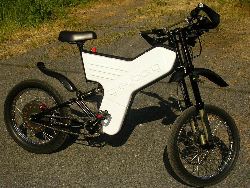
The thing I enjoy most about this space, and eBikes in general, is that we get to experiment with different setups on smaller, less expensive EV platforms -empirically- then apply those discoveries to scale up when the "right" combination is found.
Higher wind (High Torque) motors have absolutely earned their value for certain applications.
Your Mileage May Vary :wink:
Ever since the introduction (and evolution) of Justin's eBike Simulator, it has been the best place to knock around different eBike system designs ..pretty much my favorite video game.. must have literally spent days worth of hours twiddling the dials searching for the ""perfect" combination.
All those years ago, battery discharge rates were the bottleneck for achieving higher performance. SLA and Nickel chemistries were the options. Heavy with higher c-rate (and lower capacity), or somewhat lighter (and much more expensive) with lower c-rate? Hmmm..
I prefer quick over fast. Acceleration from 0 -> 25 MPH is my sweet spot.
Bursts to ~40 MPH on an eBike is my personal performance goal/limit for a go anywhere - do anything machine.
With a rudimentary understanding of Ohm's law, I started experimenting with higher voltage - lower current systems. Double the voltage + half the current = same work done; hence my preference for higher wind hub motors in smaller diameter wheels that spin up to their "happy" speed sooner than low wind motors.
Then Luke came along with LiPo batteries, and I was ruined :lol:
The thing I enjoy most about this space, and eBikes in general, is that we get to experiment with different setups on smaller, less expensive EV platforms -empirically- then apply those discoveries to scale up when the "right" combination is found.
Higher wind (High Torque) motors have absolutely earned their value for certain applications.
Your Mileage May Vary :wink:
two motors with different winds but equal copper fill will have ALMOST the same continuous power and continous torque
With common winding techniques the higher turn count motor will always have a slight edge as "dead wire" is needed to skip teeth (only to make a connection, does no work) will always be a smaller percentage of the total copper mass than that of the low turn count motor
Lets say you have a 8 turn motor and a 2 turn motor
Only 1/8 of the total wire is needed to skip teeth in the 8 turn motor while 1/2 of the total wire is needed to skip teeth in the 2 turn motor. This is only a rough explaination for visualization not the exact ratios percentage wise versus....
This can also effect the size of the motor. Imagine a hub motor with 1 turn. You likely would have to make much wider to allow clearance for the fat wire to skip teeth than an equivalent high turn count "high voltage" motor
With common winding techniques the higher turn count motor will always have a slight edge as "dead wire" is needed to skip teeth (only to make a connection, does no work) will always be a smaller percentage of the total copper mass than that of the low turn count motor
Lets say you have a 8 turn motor and a 2 turn motor
Only 1/8 of the total wire is needed to skip teeth in the 8 turn motor while 1/2 of the total wire is needed to skip teeth in the 2 turn motor. This is only a rough explaination for visualization not the exact ratios percentage wise versus....
This can also effect the size of the motor. Imagine a hub motor with 1 turn. You likely would have to make much wider to allow clearance for the fat wire to skip teeth than an equivalent high turn count "high voltage" motor
Right. I thought I made that point, here....
Miles said:The end turn losses are constant for different winds. The only thing that varies is the relative resistance of the section of copper between the coils as this changes in cross-section but not in length...miuan said:3. low number of turns usually means more interconnections between teeth and more end turn copper losses. As a result the fast motors heat more.
Yes you did but I just figured it out on my own and included the additional clearance issue
The connections between teeth and or coils are NOT end turn losses
Not often discussed but this is the key difference and why the word almost is needed
Happy new year to all!
The connections between teeth and or coils are NOT end turn losses
Not often discussed but this is the key difference and why the word almost is needed
Happy new year to all!

It's almost as neutral with respect to efficiency as changes in the number of winding turns - apart from the cases where the (re)circulating currents in delta are significant. There's been a lot of discussion about this, in the past.

teslanv
🏍️ Giga poster
So now that we know that lower-turn count motors are capable of handling more current, and thus providing similar torque output as higher-turn count motors, let's talk about what appropriate Phase current settings would be for various winds to realize this similar performance.
Let's say I have a Xie Chang 18 FET controller, and Assume a maximum rated (battery) current of 60A, and 72V nominal battery for 4320 Watts of battery power.
And let's compare the winding options of the MXUS 45mm DD Hub motor:
Would this be an accurate chart of similar torque outputs between various winding counts and Phase Currents?
21x3-Turn Wind (12 Kv): 240A --> (11.43A per strand)
16X4-Turn Wind (9 Kv): 180A --> (11.25A per strand)
12x5-Turn Wind (7.2 Kv): 144A --> (12.00A per strand)
10X6-Turn Wind (6 KV): 120A --> (12.00A per strand)
9X7-Turn Wind (5.1 Kv): 103A --> (11.43A per strand)
8X8-Turn Wind (4.5 Kv): 90A --> (11.25A per strand)
7X9-Turn Wind (4 Kv): 80A --> (11.43A per strand)
6X10-Turn Wind (3.6 Kv): 72A --> (12.00A per strand)
5X12-Turn Wind (3 Kv): 60A --> (12.00A per strand)
Let's say I have a Xie Chang 18 FET controller, and Assume a maximum rated (battery) current of 60A, and 72V nominal battery for 4320 Watts of battery power.
And let's compare the winding options of the MXUS 45mm DD Hub motor:
Would this be an accurate chart of similar torque outputs between various winding counts and Phase Currents?
21x3-Turn Wind (12 Kv): 240A --> (11.43A per strand)
16X4-Turn Wind (9 Kv): 180A --> (11.25A per strand)
12x5-Turn Wind (7.2 Kv): 144A --> (12.00A per strand)
10X6-Turn Wind (6 KV): 120A --> (12.00A per strand)
9X7-Turn Wind (5.1 Kv): 103A --> (11.43A per strand)
8X8-Turn Wind (4.5 Kv): 90A --> (11.25A per strand)
7X9-Turn Wind (4 Kv): 80A --> (11.43A per strand)
6X10-Turn Wind (3.6 Kv): 72A --> (12.00A per strand)
5X12-Turn Wind (3 Kv): 60A --> (12.00A per strand)

Alan B
📗 Minor legend
Nice comparison. Good way to "see" the effect.

liveforphysics
📜 Mega legend
teslanv said:So now that we know that lower-turn count motors are capable of handling more current, and thus providing similar torque output as higher-turn count motors, let's talk about what appropriate Phase current settings would be for various winds to realize this similar performance.
Let's say I have a Xie Chang 18 FET controller, and Assume a maximum rated (battery) current of 60A, and 72V nominal battery for 4320 Watts of battery power.
And let's compare the winding options of the MXUS 45mm DD Hub motor:
Would this be an accurate chart of similar torque outputs between various winding counts and Phase Currents?
21x3-Turn Wind (12 Kv): 240A --> (11.43A per strand)
16X4-Turn Wind (9 Kv): 180A --> (11.25A per strand)
12x5-Turn Wind (7.2 Kv): 144A --> (12.00A per strand)
10X6-Turn Wind (6 KV): 120A --> (12.00A per strand)
9X7-Turn Wind (5.1 Kv): 103A --> (11.43A per strand)
8X8-Turn Wind (4.5 Kv): 90A --> (11.25A per strand)
7X9-Turn Wind (4 Kv): 80A --> (11.43A per strand)
6X10-Turn Wind (3.6 Kv): 72A --> (12.00A per strand)
5X12-Turn Wind (3 Kv): 60A --> (12.00A per strand)
If you have a high-current controller, 16x4 is an attractive option, it's the copper fill of the 8x8, but doesn't require a ton of voltage to perform.
Similar threads
- Replies
- 13
- Views
- 896
- Replies
- 63
- Views
- 6,076
- Replies
- 9
- Views
- 6,325

- Replies
- 13
- Views
- 2,046