• Hello ES! We could use some help to get us past the finish line on building the new knowledgebase for the forum.
    Can you donate? Please see our fundraising page. Thank you!

Science, Physics, Math, & Myth

madin88 said:
there must be a reason why KTM uses 300V for the freeride-E. or look at RC model builder they also tend to use higher volts (up to 14s) and lowering current for higher overall efficiency.

Lack of taking a system level view is why so many end up at high voltages.

In the example of the Freeride, just the series diode IGBT V-drop in the controller alone is more loss than all conduction losses summed in similar powered low voltage MOSFET based systems. Yes, more losses just in the IGBT's alone than the total sum of all conductive losses from cell tab to motor in an appropriately bused lower voltage system.

They use higher voltage to waste a larger amount of the pack's energy in heating the controller, while realizing no performance benefit, but added intrinsic safety concerns of dealing with lethal voltages.

They also eat that diode V-drop if they are just cruising a light throttle loads as well as when it's making peak power.

We live in an age where we see a lot of silly stuff being done today that folks will be laughing about in a few years as EV powertrain concepts mature. Fortunately, a few folks are slowly making the realization that in an EV unlike in a large factory industrial application, the battery can sit next to the controller, and the controller can sit next to the motor, so the total power cabling length can be insignificant when compared to the cost of added BMS complexity and overcoming the intrinsic safety disadvantages of HV.
 
LFP,

Thanks for that input. One thing I've been wanting to clarify is do you EE guys have an easy solution for the low resistance and inductance loads that will come about as we search for the optimum hubmotor solutions? I've seen different brand controllers handle low inductance very differently in terms of the heat produced, but I don't understand what causes the difference.
 
cal3thousand said:
John in CR said:
Yes Mark, more turns means more torque per amp, but it's thinner copper on each turn and more turns means that thinner copper is longer, so resistance is higher resulting in more heat per amp. That also means it has lower current handling. It is all proportional such that if you treat voltage and current as variable, that different windings of the same model motor are actually the same motor. They're capable of the same power, same torque, same speed, and for the same performance they just require different voltages and current for the same power in and power out.

Regarding copper fill, the manufacturers can't always fit exactly the same total copper around each tooth for all the different windings, but the version with the most will have the lowest resistance per unit of torque, making it the most efficient of the bunch. The variance is usually small, and there are other things with far greater influence on overall real world efficiency.

John has explained this now forwards, backwards, sideways and then some. I've shed the myth towards the front of this thread and have read most of it to this point.

I will say that this particular wording is one of the most concise available on this site, hitting torque/amps, copper length vs thickness, voltage v current, efficiency, and copper fill.

Read this one over and over if you are missing the concept.

Thanks Cal. You're a gentleman and a scholar. I tend to be long-worded, so I had to hammer and hack on that post for a while before submitting.
 
John in CR said:
LFP,

Thanks for that input. One thing I've been wanting to clarify is do you EE guys have an easy solution for the low resistance and inductance loads that will come about as we search for the optimum hubmotor solutions? I've seen different brand controllers handle low inductance very differently in terms of the heat produced, but I don't understand what causes the difference.


You are seeing the control solutions to running lower inductance motors evolve nearly in real time on this forum.

We are in the covered wagon phase of EVs at this time.
 
John in CR said:
I don't recall ever recommending the use of cheap generic parts motors manufactured as substandard out of the box. I haven't recommended using undersized controllers either. In practice I use the highest performance and efficiency hubmotors available, and they're all faster wind motors. Let me know when you have a slow wind hubbie that you think comes remotely close in performance and we'll do a comparison. I prove the theory correct every time I ride using motors that require no modifications unless you push to extreme performance where cooling mods become necessary.

Motors out of the box and standard controller -> 90% here do it this way :wink:

The Hubmonster you are always talking about has a kV of 18 and i believe you pushed it above 20kW - such high kV makes absolutely sense here (together with a small wheel) and a lower kV would be a poor choice beacuse you could not use all the power / top end the motor can produce. Thats totally clear, but why you always compare your Hubmonster with other available 1000-3000W ebike hub's? Your motor is for motorcycle usage, has twice or three times the power rating and is heavy as hell! You should compare it with similar motors but not with much smaller ebike hubs.
As example Doc was running a 2T 18kV clyte motor and burned his adaptto controller because of the low inductance. Is this practical??

I also would be happy if there would be good controllers that can handle high kV / very low inductance hub's, but at the moment its not the case.
 
It should be possible to build a controller that can handle any inductive load - it just needs good control of current within individual PWM cycles. I think about the industrial SMPS, which aren't that dissimilar in function, which can handle a dead short across the output.
 
madin88 said:
John in CR said:
I don't recall ever recommending the use of cheap generic parts motors manufactured as substandard out of the box. I haven't recommended using undersized controllers either. In practice I use the highest performance and efficiency hubmotors available, and they're all faster wind motors. Let me know when you have a slow wind hubbie that you think comes remotely close in performance and we'll do a comparison. I prove the theory correct every time I ride using motors that require no modifications unless you push to extreme performance where cooling mods become necessary.

Motors out of the box and standard controller -> 90% here do it this way :wink:

The Hubmonster you are always talking about has a kV of 18 and i believe you pushed it above 20kW - such high kV makes absolutely sense here (together with a small wheel) and a lower kV would be a poor choice beacuse you could not use all the power / top end the motor can produce. Thats totally clear, but why you always compare your Hubmonster with other available 1000-3000W ebike hub's? Your motor is for motorcycle usage, has twice or three times the power rating and is heavy as hell! You should compare it with similar motors but not with much smaller ebike hubs.
As example Doc was running a 2T 18kV clyte motor and burned his adaptto controller because of the low inductance. Is this practical??

I also would be happy if there would be good controllers that can handle high kV / very low inductance hub's, but at the moment its not the case.

That's the same weak excuses you slow wind lovers came up with 5 years ago when I used the 40mm stator motor from which the Xlyte35xx, Cromotor, MXUS3000, etc. are just copies. In the meantime, you guys melted motors, and I didn't. Now that I've moved on to far superior motors, I have to hear the same thing again, but HubMonster is no heavier than the X54xx motors. Anyway once you accept about a 10kg wheel a few kg more doesn't make a hill of beans difference. If you were really concerned about weight and still wanted to use a DD hubbie, then the route to getting away with a lighter motor is to use a smaller wheel, just like it's the route to greater performance with the same weight motor.

How is one person burning up a controller by pushing it too hard using a POS craplyte motor relevant to the discussion? One controller blown by ignorance certainly doesn't balance out the scores of burned up slow wind motors used in wheels too large.

Back 3 years ago, when I was still a Myth believer too, I used to try to talk the factory into a slower winds for HubMonster and MidMonster, and they flat out refused to do it without a 100 motor minimum order paid in advance. They also told me that it wouldn't make any difference anyway except to make it a less powerful motor without going to very costly high voltage controllers. It also would make zero difference in the size wheel that could be used, because that is load dependent, not Kv dependent. Thank goodness I didn't have the money to blow on a 100 motor order, because now I know better.
 
Yah JohnCR, I took what you said to heart years ago. Here is the proof.
 

Attachments

  • small wheel.png
    small wheel.png
    120 KB · Views: 2,060
liveforphysics said:
madin88 said:
there must be a reason why KTM uses 300V for the freeride-E. or look at RC model builder they also tend to use higher volts (up to 14s) and lowering current for higher overall efficiency.

Lack of taking a system level view is why so many end up at high voltages.

In the example of the Freeride, just the series diode IGBT V-drop in the controller alone is more loss than all conduction losses summed in similar powered low voltage MOSFET based systems. Yes, more losses just in the IGBT's alone than the total sum of all conductive losses from cell tab to motor in an appropriately bused lower voltage system.

They use higher voltage to waste a larger amount of the pack's energy in heating the controller, while realizing no performance benefit, but added intrinsic safety concerns of dealing with lethal voltages.

They also eat that diode V-drop if they are just cruising a light throttle loads as well as when it's making peak power.

We live in an age where we see a lot of silly stuff being done today that folks will be laughing about in a few years as EV powertrain concepts mature. Fortunately, a few folks are slowly making the realization that in an EV unlike in a large factory industrial application, the battery can sit next to the controller, and the controller can sit next to the motor, so the total power cabling length can be insignificant when compared to the cost of added BMS complexity and overcoming the intrinsic safety disadvantages of HV.

hey mate
just a question on this, for someone (not me, this is hypothetical) who might try to design a (for example) 700kw EV (just for something ridiculous) do you think this could realistically be run with a mosfet based controller? How about issues around inductance with conductors carrying upwards of 5kA?
Basically, with current tech is there any practical power limit to mosfets and conductors? I'm sure there is im just curious as to where that limit would be... :twisted:
 
John in CR said:
That's the same weak excuses you slow wind lovers came up with 5 years ago when I used the 40mm stator motor from which the Xlyte35xx, Cromotor, MXUS3000, etc. are just copies.
The problem i have is you do not see that there is a difference between THEORY and PRAXIS.
You cannot say a high kV hub is the best choice for every situation. Thats not true because with current available controllers and without phase wire upgrades (and other mods) the overall efficiency will be worse!!
In the meantime, you guys melted motors, and I didn't. Now that I've moved on to far superior motors, I have to hear the same thing again, but HubMonster is no heavier than the X54xx motors. Anyway once you accept about a 10kg wheel a few kg more doesn't make a hill of beans difference. If you were really concerned about weight and still wanted to use a DD hubbie, then the route to getting away with a lighter motor is to use a smaller wheel, just like it's the route to greater performance with the same weight motor.
The secret to not melt a motor is monitoring temp :idea:
There is not doubt that your Hubmonster is a great performing motor and the smaller the wheel the better it is for heat generation, but you cannot say the smallest wheel is the best choice in general because it depends on many other things if it will be or not. this has been all discussed.
about unsprung weight:
John, why you do not take your bike and ride it slightly offroad or on a street that is not in perfect shape. You will see a few kg more or less motor mass make a HUGE difference and also wheel size.
On such street with not so smooth asphalt and corners i'm quite sure you would have no chance against a bike with less powerfull MXUS because you cannot put the 20kW you have - mainly in corners - on the street due to lack of traction with this heavy motor :p
I have made my experiences with this but you seem to not have - otherwise you would take this into consideration.
 
When I swapped my old 5403@15kg(with rim) to mxus@10kg(with rim) it felt like a feather during offroad rides. Maybe what we need is a motor similar to hubmonster but with bigger diameter stator/magnet ring ~24" - similar to Magic Pie but even bigger - no spokes, just smack that rubber directly on the magnet ring like hubmonster so those of us who prefer mud and dirt can enjoy smooth rides AND good torque. Dont you think we would have a powermonster?
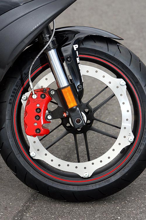
We have seen this idea on brakes for Buell MCs, even tho it was not that popular, but you get the idea:
Buell_1125CR.jpg


BTW don't underestimate the power of magic pie. It is a great performer, even with that skinny stator it has nice torque because of the big stator diameter.
 
sn0wchyld said:
liveforphysics said:
madin88 said:
there must be a reason why KTM uses 300V for the freeride-E. or look at RC model builder they also tend to use higher volts (up to 14s) and lowering current for higher overall efficiency.

Lack of taking a system level view is why so many end up at high voltages.

In the example of the Freeride, just the series diode IGBT V-drop in the controller alone is more loss than all conduction losses summed in similar powered low voltage MOSFET based systems. Yes, more losses just in the IGBT's alone than the total sum of all conductive losses from cell tab to motor in an appropriately bused lower voltage system.

They use higher voltage to waste a larger amount of the pack's energy in heating the controller, while realizing no performance benefit, but added intrinsic safety concerns of dealing with lethal voltages.

They also eat that diode V-drop if they are just cruising a light throttle loads as well as when it's making peak power.

We live in an age where we see a lot of silly stuff being done today that folks will be laughing about in a few years as EV powertrain concepts mature. Fortunately, a few folks are slowly making the realization that in an EV unlike in a large factory industrial application, the battery can sit next to the controller, and the controller can sit next to the motor, so the total power cabling length can be insignificant when compared to the cost of added BMS complexity and overcoming the intrinsic safety disadvantages of HV.
hey mate
just a question on this, for someone (not me, this is hypothetical) who might try to design a (for example) 700kw EV (just for something ridiculous) do you think this could realistically be run with a mosfet based controller? How about issues around inductance with conductors carrying upwards of 5kA?
Basically, with current tech is there any practical power limit to mosfets and conductors? I'm sure there is im just curious as to where that limit would be... :twisted:

Yes, even for 700kW, if you still can package the battery near the controller, and motor near contoller, then you still optimize around using ~100V mosfets.

The way to get stupendous power levels is to divide up the phase current into as many separate motor windings as needed. Then rather than needing a single 5kA switching controller, you can have 5x phase legs each fed by a 1kA controller (or whatever division of current makes sense for your needs and parts available to you).

This division into more phases is a proven solution for scaling up motor power within the confines of a given available controller current handling capacity.
 
liveforphysics said:
The way to get stupendous power levels is to divide up the phase current into as many separate motor windings as needed. Then rather than needing a single 5kA switching controller, you can have 5x phase legs each fed by a 1kA controller (or whatever division of current makes sense for your needs and parts available to you).

This division into more phases is a proven solution for scaling up motor power within the confines of a given available controller current handling capacity.


Very clever. I had never thought of that approach before.
 
liveforphysics said:
Yes, even for 700kW, if you still can package the battery near the controller, and motor near contoller, then you still optimize around using ~100V mosfets.

The way to get stupendous power levels is to divide up the phase current into as many separate motor windings as needed. Then rather than needing a single 5kA switching controller, you can have 5x phase legs each fed by a 1kA controller (or whatever division of current makes sense for your needs and parts available to you).

This division into more phases is a proven solution for scaling up motor power within the confines of a given available controller current handling capacity.

good point. Does it have to be multiple phases, or can it also just be parallel windings? (idk if two separate controllers would play nicely together when they're trying to push currents round the same stator teeth at the same time...)
Do you know of any examples other than john's 6ph motors?
 
sn0wchyld said:
liveforphysics said:
Yes, even for 700kW, if you still can package the battery near the controller, and motor near contoller, then you still optimize around using ~100V mosfets.

The way to get stupendous power levels is to divide up the phase current into as many separate motor windings as needed. Then rather than needing a single 5kA switching controller, you can have 5x phase legs each fed by a 1kA controller (or whatever division of current makes sense for your needs and parts available to you).

This division into more phases is a proven solution for scaling up motor power within the confines of a given available controller current handling capacity.

good point. Does it have to be multiple phases, or can it also just be parallel windings? (idk if two separate controllers would play nicely together when they're trying to push currents round the same stator teeth at the same time...)
Do you know of any examples other than john's 6ph motors?


Take a look at marine thruster motor drives. Submarines and some heavy equipment get into the 27phase range IIRC. Not because it's some substantial motor advantage over 3p or 5p, but because it's controllable with available controller tech.

Each time Silicon current density improves, the ideal EV voltage moves downward, and towards less phases required. This trend in Silicon performance improvements has been steadily occurring without signs of decreasing in the rate of improvement.

Ebikes in the sub 2kW power ranges could all be 12-24v systems easily with no loss in performance or efficiency or meaningful additional weight. This enables cheaper and less complex single chip BMS solutions (that actually work well).

ATB,
-Luke
 
liveforphysics said:
sn0wchyld said:
liveforphysics said:
Yes, even for 700kW, if you still can package the battery near the controller, and motor near contoller, then you still optimize around using ~100V mosfets.

The way to get stupendous power levels is to divide up the phase current into as many separate motor windings as needed. Then rather than needing a single 5kA switching controller, you can have 5x phase legs each fed by a 1kA controller (or whatever division of current makes sense for your needs and parts available to you).

This division into more phases is a proven solution for scaling up motor power within the confines of a given available controller current handling capacity.

good point. Does it have to be multiple phases, or can it also just be parallel windings? (idk if two separate controllers would play nicely together when they're trying to push currents round the same stator teeth at the same time...)
Do you know of any examples other than john's 6ph motors?


Take a look at marine thruster motor drives. Submarines and some heavy equipment get into the 27phase range IIRC. Not because it's some substantial motor advantage over 3p or 5p, but because it's controllable with available controller tech.

Each time Silicon current density improves, the ideal EV voltage moves downward, and towards less phases required. This trend in Silicon performance improvements has been steadily occurring without signs of decreasing in the rate of improvement.

Ebikes in the sub 2kW power ranges could all be 12-24v systems easily with no loss in performance or efficiency or meaningful additional weight. This enables cheaper and less complex single chip BMS solutions (that actually work well).

ATB,
-Luke

27 phases... bloody hell thats like 9 adaptto's! :mrgreen: :mrgreen:

Whats crazy is i've tried pointing this idea out to my supervisors for my Elec. eng final year project and even they dont really grasp the significance of it (though i'm not well versed enough in the area to articulate the point well enough either). Whats laughable at the moment is we're using a IGBT power stage for a 100V sub 20kw system :p. In many ways however thats due to lack of $$, for an appropriate motor, battery and controller. Motor is designed for 4-500V (puris motor) as is the controller. with an extra 10k in the budget the difference in efficiency would be much smaller, since we could use a 400V pack.
Regardless, its a great project for the level of control and program-ability of the controller.
 
A good project might be to investigate how the design of the prius motor could be modified for 100V use. You might just be able to re-terminate the windings to achieve it and use multiple off-the-shelf controllers :)
 
Another advantage to the higher phase counts is higher inductance for the same Kv. That's how HubMonster retains a fairly tame 70-80uH phase-to-phase inductance with a Kv of just over 18rpm/v with a 24 slot 20 magnet motor. It's wound as one 3 phase motor with 12 slots and 20 magnets with a Kv of 18 and a second 3 phase motor with 12 slots and 20 magnets with the same Kv. If wound as a 3 phase with 24 slots and 20 magnets with a Kv of 18, the inductance would be significantly lower. Run 22s and it's easy to get to 18kw peak power input with under $250 invested in a pair of controllers without running motor or controllers in a stressful manner using proper gearing for the given loads.
 
Why not send one Hubmonster to Justin for dyno test and integration in his simulator?
I believe you would have quick all the money together if you start crowdfunding like teslanv did. He collected the money for 4 MXUS motors in short time.
I would support you :)
 
I would like to learn more about the inductance of motors. I assume by the talk here, higher inductance is better and that lower inductance is not good.
Off to google I go.
 
It's not that simple. :) its all trade offs. The higher inductance slows the current ramp up which is easier for a controller to control but you cant go to far for a given voltage. Also inductance helps with feild weekening.
High rpm compact power dense motors will inherently be low inductance...
 
markz said:
I would like to learn more about the inductance of motors. I assume by the talk here, higher inductance is better and that lower inductance is not good.
Off to google I go.


From the perspective of the motor, inductance is just delayed opportunity to be producing torque.

From the perspective of the controller, inductance is the critical time delay between the FET switching on and current over-shoot blowing up the controller.

As motor controllers mature, as MOSFETs evolve for very high speed switching, and as current control algorithms get to run on faster processors with faster sensors and faster tighter control loops, then the importance of large motor inductance decreases.

Lucky for us, Silicon tech in MOSFETs get to leverage technology from the tech giant that is microprocessor development.

ATB,
-Luke
 
madin88 said:
Why not send one Hubmonster to Justin for dyno test and integration in his simulator?
I believe you would have quick all the money together if you start crowdfunding like teslanv did. He collected the money for 4 MXUS motors in short time.
I would support you :)

Madin88,

If I was really making a business of it, then I would have done that long ago. I simply make them available to ESers at as close to cost as I dare to ensure things like risk of damage in shipping are shared. If you want to spend the money to do it be my guest, but it turns out that it's wholly unnecessary.

First, the motor has already been dyno tested by Hillsofvalp. Second and more importantly, simple measurements and straight forward calculations prove the factory's test info to be true. Kv gives us Kt, torque/amp. Phase-to-phase resistance gives us copper losses. No-load currents give us all the other losses, hysteresis, eddy currents, windage, bearing friction, etc, and those vary with rpm in a manner that no-load current at 2 different rpm gives us the breakout to predict these losses at any rpm. With good input from Crossbreak Miles has done the work to provide us with a Motor Comparison Spreadsheet at https://endless-sphere.com/forums/viewtopic.php?f=30&t=65757#p989037 that does all the math for us. It's an incredibly powerful tool, because for any motor with the few simple measurements you can input rpm (essentially voltage) and torque (essentially current), and you get power out, heat broken down into it's components, and efficiency.

Instead of pressing me to spend $600-700 to send a motor that won't directly fit on any stock bicycle to Justin, you should press everyone to provide the data for every motor we can get our hands on for inclusion in the spreadsheet, so we can separate fact from fiction.
 
it sounds like it is a business. one which you have a great something but no one really knows, and you aren't interested in making a web site, and getting a business bank account, and getting the paypal button. a homegrown es motor for bikes. .. cant be beat.
 
Back
Top