OK,
time for some more test results (this time with pictures

)
I pulled out the usb scope and soldered some test leads to the positive sides of the shunt (after removing my previous shunt mod), C20, and C19. The following were done with my previous settings of 30A.
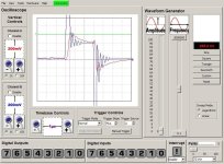
Here is the first test, Channel A (red) is the voltage across C20 at a current spike. Channel B (blue) is the voltage across the shunt, the green line is at 0.6V
you can see how the voltage across C20 closely follows the shunt voltage with just a little filtering. Also the C20 peak follows the shunt peak by less than 0.5uS, so any spike on the shunt will cause QF1 to switch.
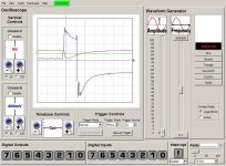
the output of QF1 is further filtered by R42 and C19. Next I measured the voltage across C19 (channel B/blue) and the voltage across C20 (channel A/red).
you can see how right after C20 goes higher than 0.6V (the green line again), the voltage at C19 goes low (causing the controller to quit).
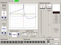
After these tests I replaced R43 with a 10k resistor (1k original). Here is the result (same setup as first test but with much longer time-base).
Note that I had to mess with the timing a little to get the controller to fault. You can see much longer/higher the shunt voltage reached before QF1 switched causing the controller to fault.
I just tested the mod by increasing the phase current to 45A. Result is that it is much better than before, however there is still a remaining problem. I can crack the throttle, and the motor will rev cleanly, but when it reaches about 1/2 full speed, it cuts. I think that even with 10k the change may not be drastic enough. Unfortunately doing this testing I think I just blew my LM317
Oh well, live and learn.
Tomorrow I will grab a replacement and then maybe I will be able to test the setup on the bike.
-Matt