garolittle
10 kW
Good information. Really appreciate the ideas. I have a “family full of lawyers” so I will be researching it carefully. Thank you.
garolittle said:That is actually a great question. I’ve often wondered the same thing. You would think there would be a $2k welder that would allow for enough power for at least .25 mm thick pure copper.Hummina Shadeeba said:Why’s there such a huge gap in welders where we can get a welder for 230$ (Kweld)that will do .1mm copper but need to spend way more to get something to do .4? Cant they just make a welder with more/bigger bits on the board?
")
nuxland said:garolittle said:[
At what voltage you new welder is working? I'm assuming more than 12V and less than 2000Amps
Usually weld at 66J - 72J at about 24 milliseconds. Not sure what the settings would be for copper thinner than .40mm but will try soon.
Frank said:Why might this welder work on .4 mm copper at those settings and the kWeld won't?
I'm not home right now but have welded thinner copper using the "sandwich" technique at those energy levels (not sure of the pulse time) but I'm pretty sure it wouldn't work for .4 mm thick stuff.
spinningmagnets said:Yeah, it's the plasma. I can't see any way to make a focused plasma jet for a few precisely timed milliseconds for under a few thousand dollars...yet.
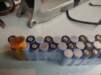
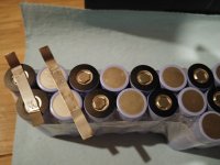
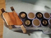
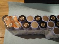
You **really** do not want **any** possibility of the batteries shifting relative to their connections.pbert said:they shouldn't move after they are taped.
...
Any reasons not to do this ?
john61ct said:You **really** do not want **any** possibility of the batteries shifting relative to their connections.
Stationary use cases are different, but bikes are inflicting massive continuous shock & vibration
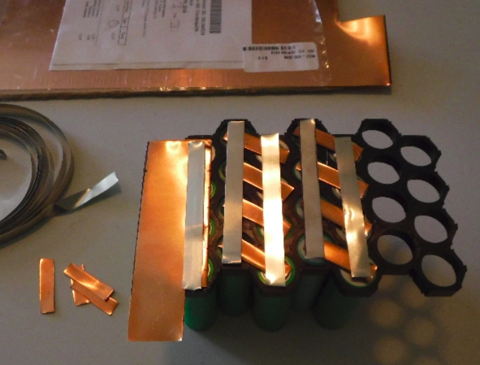
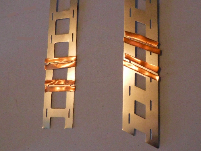
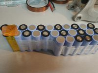
pbert said:From my understanding, current follows the path of least resistance. With this is mind, the copper is in contact with the nickel strip on the battery side as well as the nickel that is wrapped around. Therefore the current path would travel from the battery, then through 0.15 thickness of nickel attached to the battery, then through the copper to the other cells in series, through the 0.15 nickel (and in the case of the negative terminal, the copper is actually in contact with the battery directly) then into the battery. If i understand what you are describing, you are saying that the current would be going the length of the nickel and through the nickel that is wrapped around the copper and then out of those wrapped ends that are welded to the copper. This is not the path of least resistance though and from what i understand i dont think this is the way the current would flow.
For a 4p pack i think that it would be possible to have the same build as i've done for 2p. Just cut a longer length of nickel and wrap it around to hold the copper in place. The current would be evenly distributed.
I have some 0.1 copper sheet. I just tried an infinite slit with it and it welds much better than the 0.2mm copper. The problem is that the battery is putting out 60 amps continuous and so the 0.1mm copper is not enough as far as i know. I could order some 0.15mm and try with that but I would need to wait to receive it ...
spinningmagnets said:I have some 0.1 copper sheet. I just tried an infinite slit with it and it welds much better than the 0.2mm copper. The problem is that the battery is putting out 60 amps continuous and so the 0.1mm copper is not enough as far as i know. I could order some 0.15mm and try with that but I would need to wait to receive it ...
How many cells in parallel? the 2P shown at 60A would be 30A per cell.