If the chip is heating up, it was probably damaged by something else--it almost certainly wouldn't have just failed this way. The most common way is a wiring fault, either a misconnection or a short between signal level and battery level votlages in things like the motor cable or display cable where both types are present (or a throttle with a battery meter or "ignition" switch on it). This short can be very intermittent and still cause this damage, yet be undetectable when it is not actively happening (like if a cable only has the internal short when it is in a very specific position, etc.

It can also happen to someone else, who then sends the controller back to the seller as defective, who then just resells it not even testing it or caring--then the second purchaser can't even know why it's blown up, just that it is. :/
It could also be that the LVPS in the controller that makes the 5v, 12v, etc out of battery voltage is damaged or defective, and it putting out a higher voltage than it is supposed to, damaging everything on that voltage bus whether inside or outside the controller.
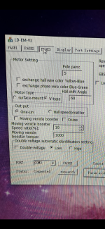
It could also be that the programming cable should be 3.3v but is 5v (there are several voltage ranges used on different serial ports), if the MCU is 3.3v inputs with direct connnections to the TX/RX lines, and that could also damage the MCU.
Those are the most common reasons for a fried MCU, if that's what's wrong.