What features do you want? Throttelizer/Throttle interface

Hi,
www.evlogix.com said:
MitchJi said:
Hi,
www.evlogix.com said:
Cruise control would be possible if it detected speed. It doesn't as of the current version, but a speed detector may be possible through an add on display or possibly an add-on speed detector.
Matt said the HV Esc's do a pretty good job of maintaining speed. In any event being able to choose a setting and have it maintained until a brake is applied would be (IMO) a good start. The brake cut-off could be either mechanical or electrical.

Wait, so the HV Esc's have a speed limiting function so you could limit the motor's RPM to a certain amount? That's cool. The current version already has an e-brake input, so it seems that could be as simple as adding wires for a user-provided cruise control push button. I'm not yet up to the task of designing things to be held onto the handlebars, but hopefully that'll change with development of the display.

Or it could be a cruise control setting that always on unless the e-brake is engaged, but that sounds like it could be dangerous.

I think Matt posted that when he hits a hill, with the throttle held steady the speed is maintained pretty close to the original speed.

I think if engaged remains on until disengaged or the brakes are engaged would be safe.
 
Yes, I can approach a hill at (for instance) 25mph pulling 500 watts. If I never touch the throttle (I use a thumb wheel with no return spring), the bike could pull well over 3,000 watts mantaining at that speed if the hill is very steep, yet I will only see maybe 2 or 3mph drop in speed while the controller ramps up current to mantain consistant motor RPM. Once cresting the hill, the wattage drops off substancially and the speed remains very consistant.

Matt
 
Ok, I think I'm understanding this more completely. So the Castle ESC software has a "governor mode"(Is that it?) that'll limit the RPM of the motor to an RPM you define if your throttle is fully engaged or "more engaged" than the throttle setting that corresponds to that RPM. To use this mode, it sounds like it would be needed to toggle between "normal throttle mode" and "current controlled mode" in the software. Technically, probably not as you could just define a really high current limit and hammer the throttle and governor mode would take over automatically in the Castle ESC's software as the motor accelerates to that RPM, but it sounds like it'd be a more intuitive choice. Anyways, adding that choice to the software would be a piece of cake.

And I think I'll add the choice of disabling/enabling and configuring the brake in the software, too.

Anyways, testing is complete! I did the technical tests yesterday measuring the current stability, temperatures, etc. and today I went for a twenty mile ride doing some uphill, off-roading and some demanding terrain, and it worked like a trooper. All seems good to go! I'm just adding a few safety features here and there (If the throttle disconnects, it won't launch the vehicle, it'll just stand still; If anything shorts, a resettable fuse protects the circuit.) and making some finishing touches. Tomorrow, I'll try to get the final prototype's enclosure completed and it'll be ready to go!

Anyways, what kind of behavior do you want the controller to have when something goes wrong? Should the board give a one-to-whatever-you-define second "stutter" and a debug LED flashes a certain amount of times to tell you what's wrong?
 
It's not a govener in the RC controller (though some do have settings for things like that). The controller runs the motor up close to the point BEMF matches pack voltage, and for that level of timing advance, it's can't feed anymore power into the motor. However, as you start to load the motor, you retard rotor position from the load, which is the same as an electrical advance in timing, and the motor can now pull more current, as the BEMF field generation vs the application of voltage across the coil are now offset due to altered magnet/coil position. This allows the controller to be able to dump much much more current into the motor than it was able to do when the motor was lightly loaded.

I recently changed the gearing on my bike (added 2 teeth to each motor drive sprocket). I can now cruise along at 64mph on a flat road, and see about 60-70amps per motor. Keeping the throttle pinned, as the road begins to slope uphill, the bike attempts to hold 64mph, and I watch current climb to around 200amps per motor. The motor wasn't able to draw any additional current when I was on the flat, but now that I'm mechanically retarding the rotor, it can apply more current, as this acts like an electrical timing advance for the motor.

Best Wishes,
-Luke
 
liveforphysics said:
It's not a govener in the RC controller (though some do have settings for things like that). The controller runs the motor up close to the point BEMF matches pack voltage, and for that level of timing advance, it's can't feed anymore power into the motor. However, as you start to load the motor, you retard rotor position from the load, which is the same as an electrical advance in timing, and the motor can now pull more current, as the BEMF field generation vs the application of voltage across the coil are now offset due to altered magnet/coil position. This allows the controller to be able to dump much much more current into the motor than it was able to do when the motor was lightly loaded.

I recently changed the gearing on my bike (added 2 teeth to each motor drive sprocket). I can now cruise along at 64mph on a flat road, and see about 60-70amps per motor. Keeping the throttle pinned, as the road begins to slope uphill, the bike attempts to hold 64mph, and I watch current climb to around 200amps per motor. The motor wasn't able to draw any additional current when I was on the flat, but now that I'm mechanically retarding the rotor, it can apply more current, as this acts like an electrical timing advance for the motor.

Best Wishes,
-Luke


I'm not sure if all this terminology refers to a concept I'm completely unfamiliar, or if it's just another way of saying you chose the gearing so that the power curve drop-off was steep near the no-load RPM so that a slight reduction in RPM from a greater loading would result in a higher current consumption to "try to keep up" to the no-load RPM, although there'd be slight speed reduction. If this is a unique concept that I obviously have no experience with, is there an online resource to learn more about it?
 
Ehh, it's not your fault, I did a sh*t job trying to explain it. I re-read what I wrote, and it seemed like bunch of jumbled rambleing.

The idea I was trying to get across is that additional mechanical torque loading on the motor enables it to draw more current, even when a controller is just running at a steady rate.

If you think about a regular 3-phase AC motor running from fixed frequency utility power, it becomes fairly simple to visualize. The motor running with no load in sync draws x current. When you apply load to the motor, you can hold the same RPM, but you've now shifted the rotor position vs the coil position, which acts like a timing advance in relation to the rotor, and the motor draws more power with the new coil/rotor position.

This is not a perfect example, as induction motors run with an inherent slip factor, unlike a PMDC motor being properly powered. I think it kinda comunicates the idea though.

I noticed you are in Wa, are you near the Seattle/Tacoma area by chance? We should meet up and you can use my bike for a test-rig.
 
Interesting. I don't understand the electromagnetic operation behind that (And I assume there's some electromagnetic explanation), but if an electronic timing advance has that same characteristic which it seems many sources confirm, then that seems understandable. So, how would this fixed RPM be implemented? In particular, what precisely does the throttle need to do to have this "constant motor RPM"?
 
I've now made shipping FREE to the continental united states and there's now a 300 amp version available. Also, if you buy two or more, you get the programming cable FREE!
 
I was thinking about how the advanced current limiting (Short user defined bursts of a higher current limit) would be implemented without a button and I thought, hey, a double twist action of the throttle sounds like a good idea! Just snap the throttle to 100%, bring it down to 0%, and snap it back up to 100% and it kicks in overdrive. How does that sound? Anyone have any other methods for engaging over-drive?

This is all controlled by software, so this and awesome future features can be downloaded without paying a dime! This is a definite advantage of digital technology where a device can be made better just by changing the software.
 
I just programmed in the over-drive current activation by double-twisting the throttle (My setting was to double the current) and, OH MAN, it's flipping awesome! Literally. It flipped me off! :mrgreen:

I'm going to try to make this as awesome as it can be! First impressions matter, I think.
 
Hi,

www.evlogix.com said:
liveforphysics said:
I noticed you are in Wa, are you near the Seattle/Tacoma area by chance? We should meet up and you can use my bike for a test-rig.

No, sorry. I apologize if you felt like this question was ignored.

It would be worth a substantial drive to ride Luke's bike:
http://www.endless-sphere.com/forums/viewtopic.php?f=28&t=8347
LiPoly powered 18HP Twin Motor Brushless MONSTER build!
bike2ip9.jpg
 
Hi,

What kind of features would you want? RC throttle

Can you incorporate a "Perfect" kill switch with plug-in spark elminator?:
http://www.endless-sphere.com/forums/viewtopic.php?f=28&t=11997&p=181503#p181503
recumpence said:
I have been thinking about a "Perfect" kill switch. You cannot just kill the center leg of the throttle POT because it is poccile the ESC can go into a fixed throttle mode and take off. It is rare, but I have had it happen to me. So, a positive disconnect is needed....

It would even be good to eliminate the plug-in spark associated with plugging the pack in. You could either setup a very simple cap charging circuit that would fire the 4110s only after the caps were charged, or you could merely use enough 4110s to handle the innitial cap charge hit...

Matt
 
MitchJi said:
Hi,

What kind of features would you want? RC throttle

Can you incorporate a "Perfect" kill switch with plug-in spark elminator?:
http://www.endless-sphere.com/forums/viewtopic.php?f=28&t=11997&p=181503#p181503
recumpence said:
I have been thinking about a "Perfect" kill switch. You cannot just kill the center leg of the throttle POT because it is poccile the ESC can go into a fixed throttle mode and take off. It is rare, but I have had it happen to me. So, a positive disconnect is needed....

It would even be good to eliminate the plug-in spark associated with plugging the pack in. You could either setup a very simple cap charging circuit that would fire the 4110s only after the caps were charged, or you could merely use enough 4110s to handle the innitial cap charge hit...

Matt

The device already goes to zero throttle if the throttle becomes disconnected. If the controller's connection becomes disconnected, there's really nothing that can be done as it's no longer connected to the controller, but I've seen that according to Castle's website for a phoenix controller,

Auto shut-down when signal is lost

So I suspect that shouldn't be a problem.

As far as a spark eliminator, it seems having a parallel battery cable with a resistor in line that you plug in first (And then main cables second, and then unplug the anti-spark cables) would be the most effective and economic solution (multiple FETs is pretty expensive for 80+ amp current capability). If it seems like there's sufficient demand for that, I might incorporate that into a future version, but for those that really want it now, they could pretty easily make a resistor-cable for pre-charging. There might be future instructions made for that purpose.
 
I'm now developing a version that's much cheaper but it wouldn't have current-limiting. I'm now taking in requests before building the design!

http://www.endless-sphere.com/forums/viewtopic.php?f=28&t=12235

Since this one would do away with current detection, you could easily have 2 temperature sensors and LVC. Also, you could add a Watt's Down display (upcoming development) to get a visual on everything. It'd still be programmable and you could turn on the throttle ramp and adjust it to how you'd like it.
 
Hi evlogix, (I posted this in your "for sale" thread, but I want to bump your thread here in the main forum too. ;) )

Nice to meet you and great job getting this far with your design!

I am VERY interested!!!

I just blew up my $100+ dollar Turnigy Sentilon (old version 3.2 )ESC because the normal "RC" throttle setup just doesn't know when current and temps are getting too high, and its' sensitivity without "intelligence" sucked.

In just a few rides I already came to hate having to think sooooo much about being super careful with the throttle...instead of just enjoying the ride!

My hand hurt from trying to keep the throttle still and controlled in an attempt to "control the current". Then I ended up making the throttle sticky so it would stay where I put it after I took my hand off of it.

Far from ideal! I had to reach my fore finger around the hand grip to grab the throttle between my thumb and forefinger to "set" the throttle "PRECISELY". Then I could let go and grab the hand grip normally (*safely*). Of coarse, if I had to make any changes to the throttle for any reason I had to start that crap all over again, or reach my thumb behind the thumb throttle to lower the throttle or "flick" it go to minimum/off. Just sad, painful, and no fun at all!!!

But having fun is why I built the thing in the first place, so I took it to Darian Lakes State Park and road it around with much less care. That's why I burned my ESC. I took my attention off the throttle (read current draw) for only 5-10 seconds and BAM, POP, SMOKE. Fun...Over. :evil:

I want one of your Throttleizer's as soon as I can save for it (AND another ESC of coarse)!!!!!!!

Just the fact that recumpence is so interested should be a green flag (pardon the pun) to the rest of us that you're on to the "right" solution.

The features you're working on are a god send my friend, and will not only save countless ESC's, but also make the ride much more fun and worry free! Which is the idea...isn't it?! :D

Thanks for doing what you are doing evlogix! I know the benefits will be self evident once people start using it! :)

It's what I've wanted all along.

I'm looking forward to all the features and optional stuff as well like the display and/or data logger.

Good luck to you and take care,
Jay
 
Yep, this is supposed to let you enjoy your beast without worrying. I don't think worrying is very fun, and I especially don't think it's very fun when you smoke a $100+ controller when you could've saved 5+ dollars by getting something that costs 95, and enjoy a smorgasboard of features you couldn't otherwise. It seems many people are currently going the servo route and I suspect many will find that spending 50 extra dollars (Online shipping costs money, too) and time just to go the "cheap" way will not be at all cheap in the long-run when they blow their controller. Like Franklin touted, "An ounce of prevention is worth a pound of cure.".

Anyways, the boards just came in. Now begins the time to assemble the boards and test each unit before they get shipped! I'll be getting the manual done that comes with wiring diagrams and other useful info so there should be little problems in set up.
 
I've now uploaded the software to my site so it can be seen and downloaded.

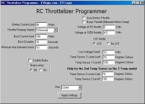
EV Logix RC Throttelizer Beta V.11 Software

Please let me know if there's anything that can be added to this software or if some thing can be improved. Please send suggestions to tech@evlogix.com .

New additions are the advanced current limit, configuring the brake, being able to choose automatic throttle or manual throttle, and being able to "bump" the lower throttle endpoint for auto throttle detection. Some cheap hall throttles have a "dead spot" or voltage dip that can cause motor creep because the auto-throttle thinks the lower voltage is zero throttle and so the resting position for throttle could cause it to think it's at a low throttle, so by bumping the low point, it effectively eliminates motor creep for those with faulty throttles. Fechter had this problem with his original hall throttle and similar hall throttles would have motor creep problems with an analog throttle interface, including servo testers.

Here's a preview shot!

RCThrotPictureLatest.jpg
 
Awesome evlogix!!!!!!!

Tell us more! Do you have any more stories, pics or vids about development and your experiences with testing?

I'm just starving for more to chew on since I can't order one just yet! :D

Have you any pics and details of the 300amp version? I would want one for the least pass through resistance even though I will only be pulling ~100amps under high loads. I plan to use 4awg wire as well.

Take care and TTYL,
Jay
 
The 300 amp version uses a .1 mOhm shunt which is pretty low. The layout of it is pretty much identical to the original, although the main power wires need to be upgraded for it. All the units so far have been designed using silicon wire which is good upto 392 degrees fahrenheit (In the design, they're good upto 240 degrees fahrenheit), but high temperatures would want to be avoided. The wires are relatively short to minimize heat and wasted power and to make the wire inductance as small as practical, to reduce the voltage spikes that the extra capacitors try to prevent from harming the ESC.

For the 300 amp version, I'm taking that on a case by case basis. If you can solder, I could provide the assembled board and you can add your own custom power wires. Or I could double the existing silicon wires which would effectively be like a 5 gauge wire.
 
There's no computer needed to change the current limit. It can be manually changed at start up using the self-programming button.

However, a programming cable would allow you to specify a more exact custom current value that would be much harder to get right with a pot/potentiometer. "Is that 160 amps or 180 amps? Can't tell." would be the person with the pot. Also, no need to add your own knob. :wink:
 
A boost button version has been made. Basically, two wires that would connect a regular on/off button are provided and this would allow one to trigger the boost current that's useful for that extra boost for acceleration or a short hill just by pressing a button.
 
liveforphysics said:
near the Seattle/Tacoma area by chance?

sorry i know its OT but dude. i head south at least 2 times a year to catch the seahawks . I just saw this and if your in that area were gonna have to hook up . let me get my bike built and we'll have to organize a westcoast rally this summer.
:D
:wink: Ot but consider it a bump EL. i like the product
 
Back
Top