Which design balances cell stress the best?

markisses

1 mW
Joined
Jul 12, 2015
Messages
19
Basics:
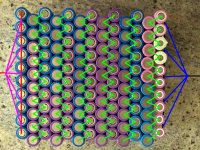
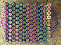
Below are four designs for connecting a 10P 13S 18650 pack that will have a 25 amp limit. All the cell to cell connections will be made with .15mm x 8mm Ni Plated Steel. The 5 lead wires (16 - 20 awg) merging into one (10 - 12 awg wire) will be all the same length.

Questions:
-Which of the designs below would be the best option for evenly stressing all the cells?
-What are some other designs that would work better these four?
-Are the gauge ranges for the lead wires okay?

Designs:
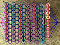
Block Battery Design_Complete 4_Small.jpg
Block Battery Design_Complete 3_Small.jpg
Block Battery Design_Complete 2_Small.jpg
 
Honestly, if you have conductors on the paralleled cells sufficient to carry all the current the group can supply, without any measurable voltage drop across it from end to end, then you only need a single series connection between each one, as long as that series conductor is also sufficient to carry all the current without any measurable voltage drop across it from end to end.


The only reason you'd have any paralleled cells under different stress than others is if the connection between the cells and the parallel conductor is not the same between each cell, and is not low to virtually zero resistance (for our purposes, that means no measureable voltage drop across the connection at the highest current that you will ever have thru it).

And if you have connection resistance variation at the cell end itself, it doesn't matter how many other connections you make *between* cells--the cell will be under different stress solely because of that connection resistance.
 
Yea, if you have series conductor alternating on the end of Parallel string the conductor length/added resistance is equal for every cell. BTW overall conductor resistance, using same materials, will be lower in zigzag pattern.
 
eTrike said:
parabellum said:
BTW overall conductor resistance, using same materials, will be lower in zigzag pattern.

Resistance between paralleled cells will be higher.
If every series has its own charge/discharge path the charge state equalization in parallel group is not of much use, considering all cells are in same health conditions.
Remember, my statement is not truth if you make pack of out of whack recycled laptop cells or such (with different capacities and resistance). :D
 
eTrike said:
parabellum said:
BTW overall conductor resistance, using same materials, will be lower in zigzag pattern.

Resistance between paralleled cells will be higher.

Is this because the zig-zag pattern creates the longest connection/path between parallel cells?
 
I would choose the third design and eliminate the common red connection from the positive side and change the green connection with resettable fuse (https://www.google.ro/webhp?sourceid=chrome-instant&ion=1&espv=2&ie=UTF-8#q=resettable%20fuse).

This way you have every cell protected.
 

Attachments

  • fuse.jpg
    fuse.jpg
    55.5 KB · Views: 760
eTrike said:
Hey PTC fuses are great. I don't have data at the moment on details to consider, but I dig the idea as they are cheap and too much safety is better than not enough. Got a build link?

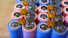
I want to use this design from here https://www.youtube.com/watch?v=5EE4TsuzD_Q but instead of soldering I will weld a small nickel sheet like here http://ecx.images-amazon.com/images/I/311TrF0Od%2BL._SX300_.jpg on the positive side to solder the resettable fuse like this http://www.ebay.com/itm/100pcs-RGEF400-GF400-4A-4000mA-16V-PPTC-PolySwitch-Resettable-Fuse-/291617827678?hash=item43e5c6eb5e:g:FqMAAOSwsFpWSg9x

I just want to rebuild my pack like this.
 
bikegeek said:
I would choose the third design and eliminate the common red connection from the positive side and change the green connection with resettable fuse (https://www.google.ro/webhp?sourceid=chrome-instant&ion=1&espv=2&ie=UTF-8#q=resettable%20fuse).

This way you have every cell protected.
:? You know that PTC fuses newer stop conduction, they raise their resistance drastically at trip point and heating holds them hi R state. This means, your parallel group still dies but you have some spare hours to notice that.
 
As long as each of your parallel/series connections is sufficient to carry the full current and not warm up, it's not going to make much difference how you arrange them. Remember that the internal resistance of the cells is probably an order of magnitude or so higher than the interconnects, and that you can't do anything about.
 
parabellum said:
This way you have every cell protected.
:? You know that PTC fuses newer stop conduction, they raise their resistance drastically at trip point and heating holds them hi R state. This means, your parallel group still dies but you have some spare hours to notice that.[/quote]

Yes but still you will notice something went wrong on your ride and you can check it at home. I've also seen that the leg of a 1/8W resistor will burn at about 5-6A, i can do the pack with that. Like a fuse used on tesla battery pack.
 
bikegeek said:
. I've also seen that the leg of a 1/8W resistor will burn at about 5-6A, i can do the pack with that. Like a fuse used on tesla battery pack.

Not if legs are soldered to cells acting as heat sinks. I believe, Tesla uses kind of alloy with extraordinary crappy thermal conductivity and low fusing point. BTW your solder will flow before leg blows and you do not want liquid metals flowing down those positive poles.
 
bikegeek said:
Take a look at this video https://www.youtube.com/watch?v=raBWFsPlx7w and see the test that guy is doing. From here I got the idea.
This guy is not taking in consideration a lot of things, the length of the wire, thermal and electric conductivity, thermal mass and thermal path. I bet those short cell connections somewhere in the middle of bus bars can take over 4x the current fusing this long wire on the end of the bar and what looks like bad thermal path on the wire (see how solder on the wire got liquid just before fusing)
Your idea (edit:about fusing itself) is good, I did something similar time ago, before I understood mentioned problems. First best thing you can do is not using solder on cells. :wink:
 
999zip999 said:
You need a gasket on the pos. end to protect against a short with the negative can. Are you planning on a bms ?

Gaskets on the positive terminals and insulation between the groups connected in series are always a good idea and planned for the pack. Besides adding a BMS, which of the designs originally posted do you believe would equally balance the stress felt by each cell?
 
bikegeek said:
I would choose the third design and eliminate the common red connection from the positive side and change the green connection with resettable fuse (https://www.google.ro/webhp?sourceid=chrome-instant&ion=1&espv=2&ie=UTF-8#q=resettable%20fuse).

This way you have every cell protected.

Would you at least have a parallel connection on the first set of positive terminals for the first set of parallel cells so that you could attach your positive lead(s)?

If not, how would you connect your positive lead to the pack?

Basics:
Below is a design, suggestion by bikegeek, for connecting a 10P 13S 18650 pack that will have a 25 amp limit. All the cell to cell negative parallel connections will be made with .15mm x 8mm Ni Plated Steel (pure nickel would be better). The series connections (orange) will be fuses of some sort. The 5 lead wires (16 - 20 awg) merging into one (10 - 12 awg wire) will be all the same length.

Design:
 
If you will use fuses I would use a fuse on every cell positive and after that I would connect them in parallel.

And the diameter of the wires should be a little bigger then the wires from the controller or the motor. For my pack I used very thick wires and when I connected them to the controller I've seen that the controller had 2x smaller wires :) If they are to thick you will have problems with bending them for fitting the bike or the chassis.

I'm still a fan of using fuses on every cell but I don't know which system to use. Till know both system I found uses soldering and I don't know how to avoid this.
 
bikegeek said:
If you will use fuses I would use a fuse on every cell positive and after that I would connect them in parallel.

And the diameter of the wires should be a little bigger then the wires from the controller or the motor. For my pack I used very thick wires and when I connected them to the controller I've seen that the controller had 2x smaller wires :) If they are to thick you will have problems with bending them for fitting the bike or the chassis.

I'm still a fan of using fuses on every cell but I don't know which system to use. Till know both system I found uses soldering and I don't know how to avoid this.
Then take a look at attached sheet. Metals are sorted the way they make most sens using as fuse material concidering only thermal and electric properties. Its basically Electrical conductivity/Thermal conductivity/Melting point x 10000(to take all zeros away :D ). BTW, there are much more factors too analyze, economical, chemical, galvanic properties etc.
 
What cells are you using ? Number 1 is fine. Parallel string acts as one cell and only needs a small gauge connection. series needs a heavier connection. I'm more concerned with how well your cells are matched. As your battery is only as strong as your weakest cell. Plus your biggest problem is not heating the positive end...
 
Back
Top