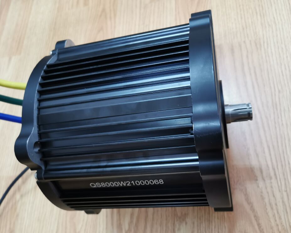
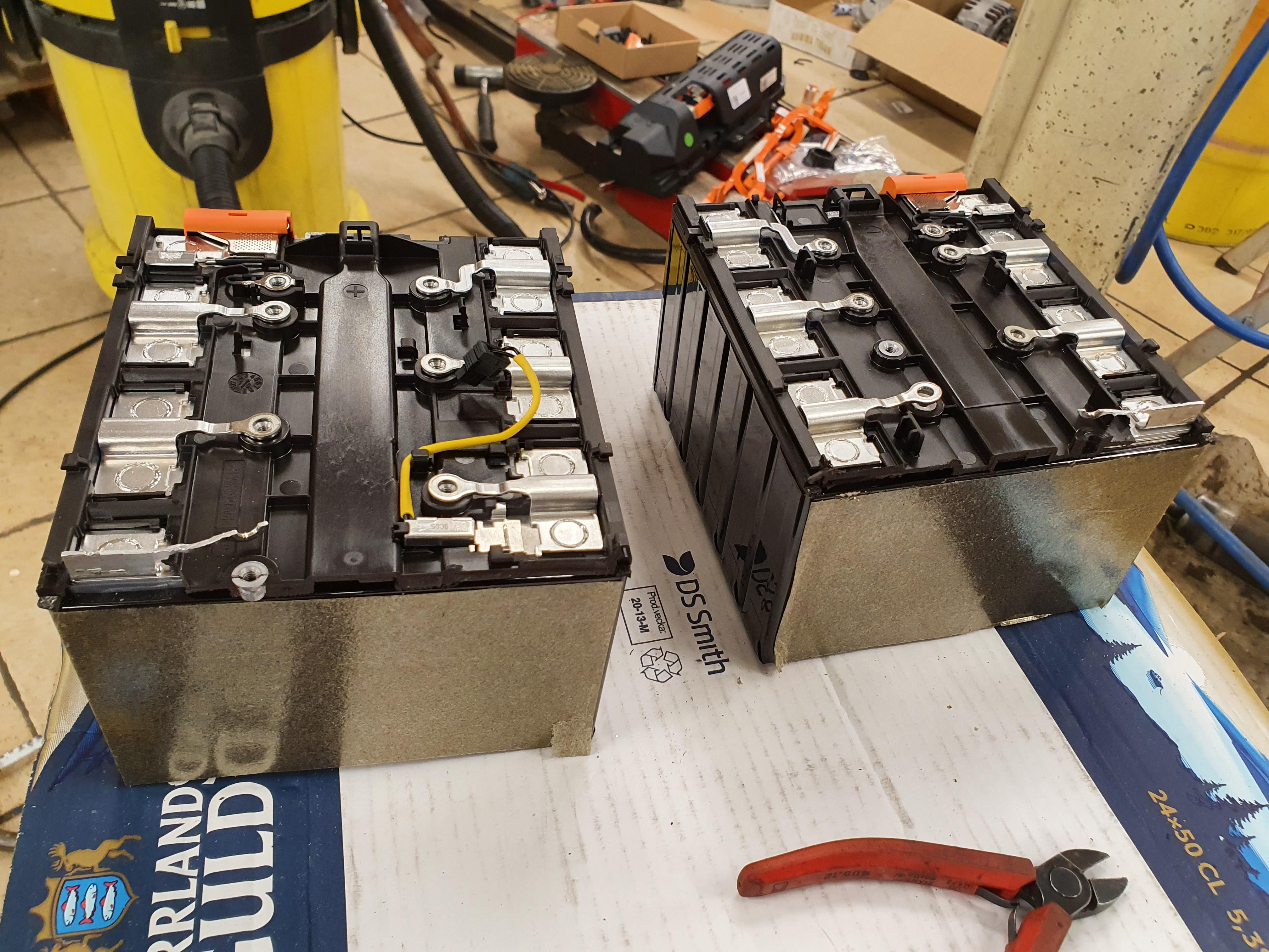
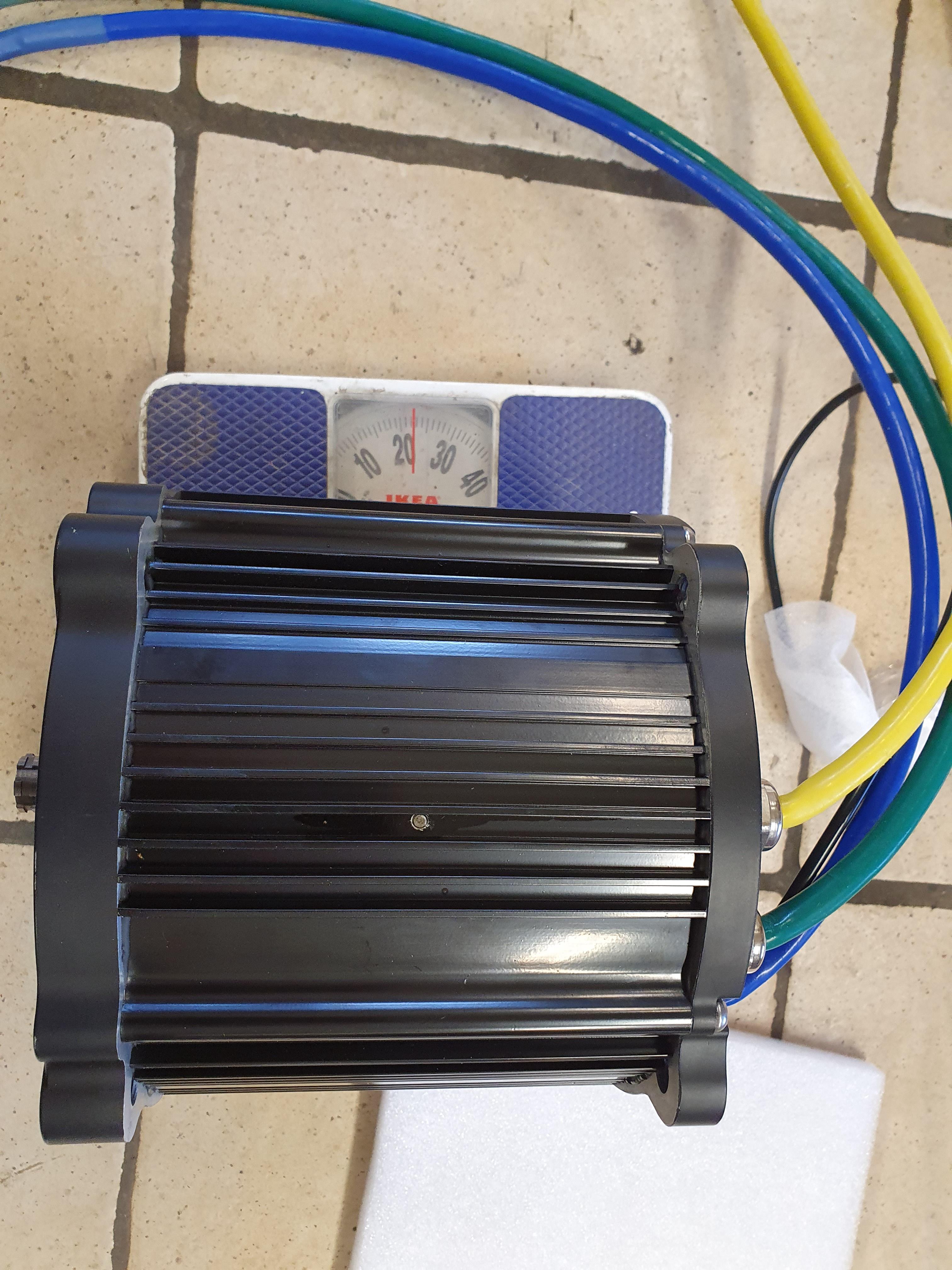
Yamaha YZ250F

j bjork said:
The middle section should have been flipped 180 degrees.
To fix this the motor would have to be rewound.
Is this for real?!

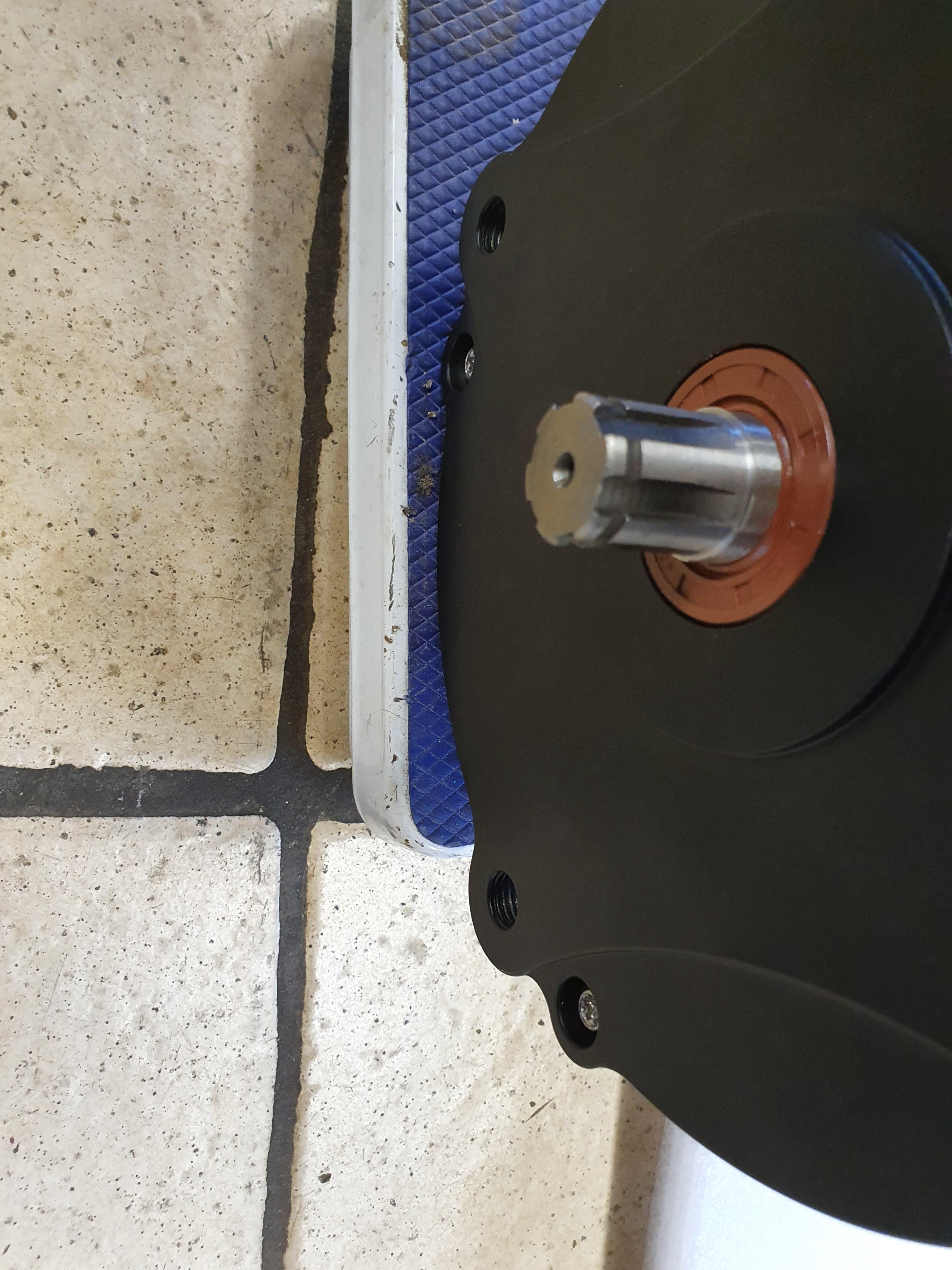
I think you are right, they have flipped the finned case. If it was placed correctly there will be room for the bolts and the finned part would be in the right place.
Good luck trying to explain this to them...but probably it's the only thing you can do now. :(
 
I cant see how they have possibly missed it trough production and all the way to start deliver to customers.

I missed it at a quick glance at a picture, then at a second look I saw it almost immediately.
They must have seen it, but choose to ignore.

Probably like my mails yesterday, first I replied "very good" and asked them to ship as soon as possible.
Then right after I replied again pointing out the problem.

A few hours later I got a reply on the first mail..
 
Looking at the pictures they have on their website, it seems the problem was there already!

http://www.cnqsmotor.com/en/article_read/QSMOTOR%207000W%20180%20electric%20bike%20mid%20dirve%20motor/875.html
20190226150104_604.jpg
 
That is just some pre production rendering that is on their website, it is not the same as the production motor.

But I might have misunderstood, the flat surface may be the identification numbers.
The 10,5mm holes may be planned for M12x1,5 thread all the time.

I got some more pictures today to look at in the evening.
 
j bjork said:
That is just some pre production rendering that is on their website, it is not the same as the production motor.

:lol: I am sure these are not renderings, but pictures (in low resolution and probably some cutting/mask) of the real thing.
They are certainly not that good in making a surface reflection like that on the flange.
There is also another shot of the back, with the phase wires and resolver cover.
 
Ok, probably a bad choice of words. I mean that it is a model or a pre production test unit that looks different than the production unit. On that they didnt have any mounting holes in the rear cover, and it seems to be a longer one that should need it more.

That also seems to suggest that it was meant to be threaded holes in the cover all the time.
 
One of the flat surfaces sure is for the specification:

ASdqqop.jpg


FBzCYLF.jpg


But it looks like there are one flat surface that would have fit for every bolt hole if the center section would have been flipped around.
Well, If I will be using short bolts threaded in to the covers it dosent matter much.
 
I made a little box for the battery:

wYImf7k.jpg


It is about 5mm thick, that is about what a fiberglass box with 4 layers would be.

Guess what, it didnt fit:

mzfEheP.jpg


The nice cooling plate between the modules had to go.
I didnt plan to have a water cooled pack anyway, but it would have nice to have the alu for some inertia.

So the alu plate had to go, and after cutting down the box it fits:

XgpiQ0Z.jpg


I would have liked some more play, but maybe I can grind a little here and there to get some clearance.

I got this bad boy today too :wink:

qwDfRiJ.jpg


This is not where it will be mounted, it is just to show that it dosent really fit anywhere..
 
AXFTlUE.jpg


If you don't mind me asking, I think these modules might be popular for other builds. Would you please post the precise external dimensions of a brick? And how many cells per brick?

Did they appear to be able to be broken down into smaller pieces?
 
One module or brick contains 12 cells in 12s 1p configuration, and is 352mm long, 151,5mm wide and 109mm high.
One cell is about 148mm wide, 27mm thick and 91mm high without any connections on top. So in reality it will end up at least 5-10mm higher.

They can be split up just like I have done in the picture. The trickiest part was to cut the plastic on top of the cells without damaging the cells. If you want to split them in to single cells you can probably just cut the busbars and slide the cells out of the plastic top.

If you cut the bus bars in the middle you will end up with a piece that is about 20mm wide and 10mm long on each cell.
They are welded on the cells, so it is not easy to add your own connection to the cells.
I plan to drill 2 holes and screw or use rivets.
 
I have the motor now :)

7L6JH8Y.jpg


It weights in at about 22,5kg on my bathroom scale.

I still think they have flipped the middle section, there are 4 of these blank areas that would have lined up with the holes if the middle section was the other way around.
But the holes are threaded with M12x1,5 so it will not be a big problem.
I will just have to cut the bolts in the right length so they dont go through the end covers.

hx5oiw5.jpg


There is another problem though, they used another spline then the usual for the 20mm shaft.
This is 20x17 with a 5mm spline, instead of the 20x16 with 4mm spline I have on my qs 138 70h

I found this sprocket:

WdcpOSW.jpg


The problem is I want probably 11 or 12 tooth for 428 chain.
If someone know of a sprocket like that, please let me know.
 
I am trying to get my parts for the motor mounts water cut, but the company didn't want my paper sketches or wood models..
They want cad drawings, people are so picky these days :wink:

The problem is I didnt know how to make cad drawings.
I have been struggling in the evenings and a big part of the weekend, but suddenly I got a hang of it :)

abhBgXW.jpg


The plan was to finish all of them during the weekend, but that is not going to happen.
I have made the easier ones, but I will go back and have a second look at them.
Then I have the trickiest left to do..
 
What kind of cad are you using? I recommend Fusion 360 (free for personal use) to make this kind of sketches (that you can easely transform in 3d plates). It's easier to use than any traditional 2d cad as autocad, you will learn the basics in a few hours with the tutorials. And the basics are all you need in this case.
The major benefit is that is parametric: once you have set up your geometry with quotes and relations, you can change anything easely without having to redo the whole thing. Once tried, you will never go back to a traditional non-parametric cad.
 
Finally I have finished all my drawings.
I bought a printer so I could print them out and compare to the models to make sure:

pEyxAMR.jpg


It was a good thing that I did, the 2 holes that fits in the standard holes in the frame on the right side was about 3mm off.
So now I hope it was the drawing, and not the model that was wrong :wink:

They are sent to the cutter now, so I will just have to wait and see what he says.
 
Back
Top