Definitive Tests on the Heating and Cooling of Hub Motors

Here is a summary of most of the test data acquired from the past couple weeks. I'd like to publicly thank Akshiv, a junior engineering physics student we've had on a short work term here, who has painstakingly run most of the experiments and number crunching.

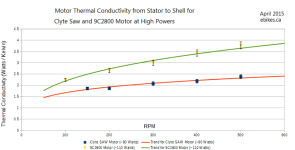
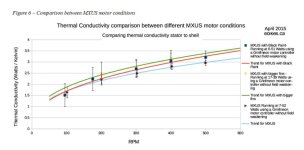
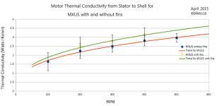
When we started these tests, we decided to see how well it would work as a methodology to simply run the motors unloaded at various speeds and wait for the temperatures of the motor core and shell to reach equilibrium, because this is a technique that almost anyone could replicate on their own with no fancy equipment. The downside is that the power going into the motor is quite low, on the order of 10-40 watts depending on the motor and RPM, and so we are dealing with much lower temperature variations than what you would have in practice with a loaded hub. I'd previously summarized these results on the 3 motors under test (the small SAW20 motor, the 9C hub, and the 45mm wide MXUS hub), and here it is again with error bars and also including the run with the MXUS motor having radial fins installed on the insides of the side plate:
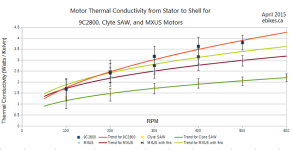
Comparison between Motors at Low Powers.PNG

You can see that the fins did improve things about 10-15%, but still not enough to equal the thermal conductivity of the narrower 9C motor,
Comparison between MXUS with and without Fins.PNG

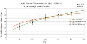
The question we also wanted to answer was whether the heat conduction term was constant enough over temperature differentials that the values measured at low unloaded powers extrapolate to the high power regime OK? Normally to test the motor at high watts of heat you would need to load it down. But that gets complicated mechanically, and electronically it also means that you can't simply measure the electrical watts going into the hub to figure out how much heat is generated as a majority of the input power is doing mechanical work against the load. We had actually purchased some rolls of nichrome wire that we were going to embed to the inside of the stator to give us a controlled thermal input from a heating element and external power supply, but then realized we could achieve the same effect much more easily by using a field oriented motor controller and setting a large field weakening current to apply at all RPMs.

With the 9C hub, we set the field weakening current to 30 amps, so even though the unloaded draw of the motor is just like 1-2 amps, there is on top of this 30 amps of out-of-phase current flowing through the phase wires doing nothing but fighting the field of the permanent magnets. That way we can have an appreciable amount of I^2R heat generation, exactly like if the motor was being loaded to 30 amps, but without the complexity. And because there is no mechanical power coming out of the spinning motor, we can conclude that all electrical watts going into the system is turning into heat in the core. For the different motors, we adjusted the field weakening currents so hat the motor core temperatures reached steady state in the 100-130 degree range.

For the 9C motors, the heat conductivity terms measured at high powers like this were very similar to the lower power unloaded tests, within the margins of measurement error:
Comparsion between High and Low Powers in the 9C2800 Motor.PNG

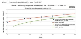
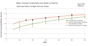
With the smaller SAW20 motor, there was a definite increase in the thermal conductivity at the higher temperature tests than the unloaded tests:
Comparison between High and Normal Powers in the Clyte SAW Motor.PNG

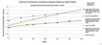
Comparison between Motors at High Powers.PNG

From now on we'll be using this technique with field weakening to get higher heat input levels.
I've gotta leave for the next 4 days but once back we will have the test data for the MXUS motor with the side covers and core painted.
 
I hope to be getting up photos of my heat sink mods next week as soon as my wife returns home from vacation with her digital camera.


I had a question to the people that have spray painted their coils/ magnets/ internals with a coating/ urethane to prevent rusting issues.


What specific product did you use , did you bake it in a oven at a certain temp for a certain period of time , to cure it better, and has it flaked off at all ? Also, do you think the coating has hurt efficiency at all ?
 
I just ordered different sized heat sinks...to experiment more...

I have question .

Does anyone know for sure, if a heat sink that has a base plate that is 4.5 m.m thick will conduct heat better/ quicker to the fins of the heat sink then a heat sink that has a base plate that is 2m.m thick ?

In other words, does a thinner or thicker aluminum base plate result in quicker/ better removal of heat to the heat sink fins
 
ebikedelight said:
I just ordered different sized heat sinks...to experiment more...

I have question .

Does anyone know for sure, if a heat sink that has a base plate that is 4.5 m.m thick will conduct heat better/ quicker to the fins of the heat sink then a heat sink that has a base plate that is 2m.m thick ?

In other words, does a thinner or thicker aluminum base plate result in quicker/ better removal of heat to the heat sink fins
I think you should look at "Thermal Resistance @ Natural" column.
http://www.digikey.com.au/product-search/en?FV=fff40012%2Cfff80068&mnonly=0&newproducts=0&ColumnSort=-922&page=1&stock=0&pbfree=0&rohs=0&quantity=&ptm=0&fid=0&pageSize=100

Edit:

Justin,
Should I be converting to Kelvin? The difference would be the same AFAIK.
Also, looks like you've verified the low power model is legit, relative to higher realistic power...?
 
Justin, Thanks for these awsome test data.

I am wondering if the stator core width have something to do with the thermal conductivity from stator to shell ?

I mean if we double the stator width ( nearly doubling the copper fill and btw the rated power before saturation) the total radiating surface of the shell does not increase by the same factor...

So would the very large motor shell diameter with narrower stator core have better thermal conductivity than smaller diameter with wider stator core?

In other word the shape of the motor might have also something to do in relationship with the thermal conductivity of rotor to shell?


Btw, Flat black mat dont have all the same emissivity. I tested at work some back BBQ style paint and some specialized flat black paint like the Krylon 1602 and also the well known 3M black velvet used in the astronony and the absorptin graph have like 10-15% diff in emissivity over al the spectrum...

I the IR range we should not use what our eyes see as black but what a REAL IR SPECTROMETER say.. and i did that test.

It appear that the surface roughness of the paint have something to do with teh IR absorption and spectrum. The real flat black that goes far in IR are more rough witch capture more radiating flux due to the surface that trap the light ad increase the number of reflections while it penetrate the deepness of the black layer.

The paint you used inside your side cover look like having some reflections and having a smootr surface that you also get specular reflection on it pretty easy. A real IR absorptive paint like the Krylon 1602 or the 3M Black Velvet 811-21 dont have any specylar reflection in any angle and look like a black hole... lol

I am not saying it will double the heat absorption but i'm saying that with a better paint results could be improved.

If you want i can send you a 3M black velvet kit for test as well as a Krylon 1602 spray can. these are real flat mat black!

This is also the one they use for Black Body construction and also that Gentec use for their thermopile. :wink: Pm me if you are interested!

Doc
 
does the black Krylon 1602 hold well on aluminum, stator and windings, or does it need priming? i was not able to find any infos about this using google
 
madin88 said:
does the black Krylon 1602 hold well on aluminum, stator and windings, or does it need priming? i was not able to find any infos about this using google

I usually use primer that i let dry and then apply 1 thick coat of Krylon 1602. But it hold great on orbital sanded (180 grid) and cleaned aluminum.

Doc
 
Doctorbass said:
Btw, Flat black mat dont have all the same emissivity. I tested at work some back BBQ style paint and some specialized flat black paint like the Krylon 1602 and also the well known 3M black velvet used in the astronony and the absorptin graph have like 10-15% diff in emissivity over al the spectrum...

I the IR range we should not use what our eyes see as black but what a REAL IR SPECTROMETER say.. and i did that test.

It appear that the surface roughness of the paint have something to do with teh IR absorption and spectrum. The real flat black that goes far in IR are more rough witch capture more radiating flux due to the surface that trap the light ad increase the number of reflections while it penetrate the deepness of the black layer.

The paint you used inside your side cover look like having some reflections and having a smootr surface that you also get specular reflection on it pretty easy. A real IR absorptive paint like the Krylon 1602 or the 3M Black Velvet 811-21 dont have any specylar reflection in any angle and look like a black hole... lol

So both standard flat blacks brands were about the same, but the non standard bbq grill paint that is made easy to clean (read slicker not truly flat) was not as good :lol:

You are right about surface roughness. The blackest known material is actually standard metal hit with femtosecond laser pulses. The surface becomes like a dense forest and absorbs almost all visible light, but the absorbtion extends into the far infrared. More importantly it is one of the only way to absorb terrahertz freqs (stealth hint). When you look at it next the normal flat black the flat black appears grey as your eyes inperpretation is relative not absolute. Truly pitch black and no peeling paint.
 
any news?
 
madin88 said:
any news?

Yes! So we wrapped up the bulk of the Stator -> Shell heat flow characterizations back in April. The end result is that black paint on the MXUS side covers had a small but measurable effect when dealing with small heat dissipation levels, even at low RPMs, while adding large fins to the inside of the side plate made a more substatntial improvement in conductivity, but it's still just on the order of 10% or so. Not exactly a night and day difference.

MXUS Stator to Shell Conductivites.jpg

And here is the comparison of the 9C, Crystalyte SAW, and 45mm MXUS motors' stator to shell conductivity as a function of RPM when using field weakening in order to get more substantial power levels (aiming for a ~100oC core temp). The best fit curves are of an exponential variety, Conductivity = A0 + A1 ^ (K*RPM). From the literature we were expecting the exponent to be approximately 0.5, and this is close to what we saw, although we're not sure why the 9C motor shoed almost a linear type of dependency.

Various Hubs Compared.jpg

There was also a definite increase in thermal conductivity with the amount of power dissipated in the core. At first we were just using the no-load current to heat up the stator, but that would only be on the order of 10-40 watts of power. When we used field weakening in order to get a large IR^2 copper loss in the mix so that the heat levels were more representative of riding the motor under load, then at those higher temps the heat flow increased about 20%. This would make since since both self convection would increase from the hotter core, and the radiation component would start to play a bigger role too with the hotter cores.
High vs Low Power Thermal Conductivity.jpg
 

Attachments

  • Motor Heatflow, Draft Coop Report.pdf
    1.1 MB · Views: 273
The next step for a complete thermal model requires a characterization of the heat flow from the motor shell to ambient. When we did the stator->shell conductivity tests we took pictures with an IR camera to get the motor shell temperatures, and found that the temperature variation across the entire outside of the motor didn't usually vary by more than +- 1 degree or so, with the exception around the motor axle where which is hotter both because of the I^2R heat generated by the phase wires going into the hub, and because the axle is thermally coupled to the much hotter stator.

MXUS Side Plate Temps.jpg

So that validates the idea that we can treat the motor shell as its own thermal mass that is at a uniform temperature. But the ability of the hub shell to dissipate heat to the environment depends not only on the RPM but even more so on the air flow as a result of forwards motion of the bike. You may recall that in the earlier tests I placed a fan near my motor dynamo in order to simulate some wind speed over the hub, which measured around 12 kph. ( http://endless-sphere.com/forums/viewtopic.php?p=722338#p722338 )

But what I really want is a full plot of the thermal conductivity vs. wind speed from 0 up to say 50 or 60 kph. And to get an controlled wind speed in our lab with the motor under test, we need a Wind Tunnel!

Fluid Mechanics is not my strong point but NASA has a ton of great information on designing and building wind tunnels. So starting here:
https://www.grc.nasa.gov/www/k-12/airplane/shortt.html

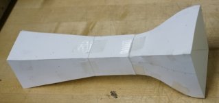
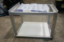
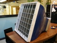
We came up with a design using a 3' x 3' bell, tapering down to a 16" by 16" test section for the hub motor to spin in, and then expanding outwards to a 24" diameter fan since that seemed like a relatively common size of fan blade to find online. There is a nice spreadsheet from the NASA site for creating the cubic spline curve for the reducer profile which we tested on a paper template
Wind Tunnel Model.jpg

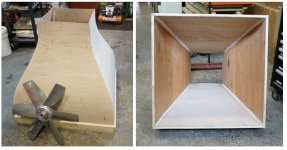
Then used thin 1/8" doorskin plywood and the "stitch and glue" style of boat assembly to to make the full sized curved reducer section, which worked out quite well. The blade fan is an industrial 24" diameter unit we found on ebay with solid aluminum vanes, way tougher feeling than the normal stamped sheet metal variety.
Wind Tunnel Bell and Fan Blad.jpg

Soo, as a result of all this pursuit, much of the work on the thermal testing in the last 5-6 weeks has centered on getting this wind tunnel finished up so that we can run phase 2 of the experiments.

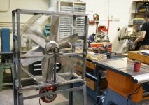
For those interested in the building of test equipment I'll share some details here. The fan itself we've got rigged up in a metal frame to be driven with a stokemonkey motor from a regular ebike motor controller, and we'll have a Cycle Analyst with an anemometer as the speedo input so that we can use the CA's speed limiting feedback loop in order to maintain constant wind tunnel air speeds.
Wind Tunnel Fan Section.jpg

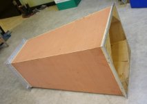
In front of the fan is the diffuser which slows the air down from the 16" x 16" test section to the 24" fan and changes the tunnel shape from square to octagonal
Wind Tunnel Diffuser.jpg

The test section is clear plastic with a removable wooden base for securing the motor support and holding all the probes and whatnot. We're in the process of building a side plate with an access window too:
Test Section.jpg

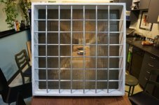
Here's the bell after a bit of finishing work. There's a honeycomb mesh for straightening the air flow coming into the tunnel and a grid of 1/2" diameter metal tubes to protect the rather delicate mesh from getting mashed.

Wind Tunnel Bell, Finished.jpg

We were quite lucky to find a guy from the movie effects industry selling 5' x 3' honeycomb aluminum sheets on Craigslist, otherwise it would have been the very tedious task of cutting and gluing thousands of drinking straws into a grid. He apparently got them from a contact in the rail industry which has them for high performance train fabrication, but needed them in the film business as a simple way to produce directional lighting. Optically the stuff is pretty trippy to look through:
Honneycomb.jpg
 
Great work, look forward to see the final results with the wind tunnel working.

So heat sinks inside the motor helps. Imagine connecting those heat sinks via heat pipes to another set of heat sinks mounted on the outside of the side covers. Then we should see effects both via added thermal masses, closed loop liquid cooling from heat pipes and faster cooling of the outside heat sinks due to the wind tunnel blowing over the heat sinks so that in turn should speed up the transformation from gas back to liquid again and thereby make the heat exchange more effective and the overall cooling even more effective.

Any chance you could add a second set of heat sinks to the outside of the side covers, and connect each of them to an inside heat sink via heat pipes? As this has potential for being the ultimate closed loop cooling system I hope you can give it a try. Imagine effective cooling of hub without the added risk of rainwater/debris filling the hub like mane fears when cutting cooling holes in the side covers.

Example of heat sinks connected with heat pipes:

3_9342_heat_pipes_600.png


Heat pipes:

famk_thermal_fundamentals_2_nov2011.gif
 
macribs said:
Any chance you could add a second set of heat sinks to the outside of the side covers, and connect each of them to an inside heat sink via heat pipes? As this has potential for being the ultimate closed loop cooling system I hope you can give it a try. Imagine effective cooling of hub without the added risk of rainwater/debris filling the hub like mane fears when cutting cooling holes in the side covers.

Yes exactly, I've also been increasingly convinced that this would be the best overall approach to motor cooling while still allowing for a sealed hub. Open vent holes work great, but I can understand that any motor manufacturer / ebike vendor would be quite reluctant to have a motor with the insides totally exposed to the elements like this. With heat pipes, you can keep the hub internals mostly sealed and move the heat out to a finned heatsink mounted to the fork or similar in full air flow.

I actually picked up a bag full of laptop heatsink/heatpipe assemblies from a scrap metal yard not too long ago for experimenting on this, although on doing further reading it seems that we'd need a heat pipe diameter on the order of 1/2" in order to deal with the 300+ watts of heat extraction from a loaded hub, which requires a larger than normal axle bearing to pass through. A smaller diameter pipe (like those salvaged from laptops) could pass through a normal ebike axle but wouldn't be able to cope with typical heat flow requirements.
 
This is some awesome work Justin, thanks so much for contributing to the community like this. :)

I think hub motor manufacturers should pay attention...I predict the first manufacturer to build in some enthusiastic heat shedding tech (like heat pipes) to their hub motors would make some killer sales.
Much like the first manufacturers of fully enclosed CPU water block + radiator/fan coolers were able to corner the market before the other manufacturers caught up.

Justin, have you been following, or considered doing similar to our efforts with internally mounted fans inside hub motors?
http://endless-sphere.com/forums/viewtopic.php?f=30&t=56965&start=100#p1009838
I'm on my second motor with this mod now, and it's working well. :)

Cheers
 
justin_le said:
macribs said:
Any chance you could add a second set of heat sinks to the outside of the side covers, and connect each of them to an inside heat sink via heat pipes? As this has potential for being the ultimate closed loop cooling system I hope you can give it a try. Imagine effective cooling of hub without the added risk of rainwater/debris filling the hub like mane fears when cutting cooling holes in the side covers.

Yes exactly, I've also been increasingly convinced that this would be the best overall approach to motor cooling while still allowing for a sealed hub. Open vent holes work great, but I can understand that any motor manufacturer / ebike vendor would be quite reluctant to have a motor with the insides totally exposed to the elements like this. With heat pipes, you can keep the hub internals mostly sealed and move the heat out to a finned heatsink mounted to the fork or similar in full air flow.

I actually picked up a bag full of laptop heatsink/heatpipe assemblies from a scrap metal yard not too long ago for experimenting on this, although on doing further reading it seems that we'd need a heat pipe diameter on the order of 1/2" in order to deal with the 300+ watts of heat extraction from a loaded hub, which requires a larger than normal axle bearing to pass through. A smaller diameter pipe (like those salvaged from laptops) could pass through a normal ebike axle but wouldn't be able to cope with typical heat flow requirements.

I might be wrong here, but why care about the axle? If you inside heat sinks are glued to the inside of the cover why not just glue some outside heat sinks to the outside covers? The inside and the outside spins at the same speed. And you can circumvent the need for one large pipe by using several smaller pipes.

What I picture is several heat sinks on both sides of the motor covers. Connect inside heat sinks to outside heat sinks via heat pipes, drill the hole straight thru the side covers for the heat pipes. Put some high temp resistance epoxy around the pipes blocking the entry holes for the heat pipes. Perfect closed loop and no holes for water and debris.

@cowerdly lucky I totally agree man. QS or other manufacturers should pay attention in class and put some extra effort into it. Now we know flat black paint inside will help. We know heat sinks helps. So QS - shut up and take my money! Give us what we want and more will follow. Flat black paint inside, heat sinks inside and out and heat pipes connecting them. Pls listen to us.

For people living up north like I do, we have 4-6 months of cold weather. And during the cold periods they spray the roads with salt and saltwater solutions to avoid icing and that shit is not something you would like to have inside your motor. All that salt turns any metal into crap. Even aluminum shows signs of salt - it does not rust like steel and iron but the aluminum evaporates somehow.
 
Incredible work Justin! what a nice R&D !!!

Maybe there is something i can share about axel thermal conductivity from my recent experience.

i've been using the 5403 beef hub motor on my DH bike with 10kW+ and about 2 years ago i modified it for liquid cooling, but after i finished the intense motor modification for the liquid channels and I/O pipes, i was too lazy to finish the installation of the 3x 120mm fan heatsing combu and pump and feft the motor as is on the bike.

What surprized me is that even with 3kW average ride and burst to 12kW, the motor winding remained under 120 celsius!!!

I observed that there was more than normal heat on the axel and even the swign arm! so it look like the added aluminum disk in sandwich to the stator structure helped to conduct heat to the axel.

To give you an idea of the added metal to the stator Here are the pictures of my modified 5403 motor:

file.php


file.php


file.php


file.php


file.php


file.php


file.php


file.php


file.php


file.php


file.php


file.php


file.php


file.php


file.php


file.php


file.php


file.php


file.php


file.php


file.php


file.php


file.php


file.php


file.php


file.php


file.php


file.php


file.php


file.php


file.php


file.php


file.php


file.php


file.php


file.php


file.php


file.php


file.php


file.php


file.php


file.php


file.php


Doc
 
macribs said:
I might be wrong here, but why care about the axle? If you inside heat sinks are glued to the inside of the cover why not just glue some outside heat sinks to the outside covers? The inside and the outside spins at the same speed. And you can circumvent the need for one large pipe by using several smaller pipes.

We're not trying to conduct heat from the inside of the side cover to the outside of the side cover, the aluminum motor plates themselves do an almost perfect job of this. We're trying to conduct heat from where it's generated at the non-rotating Stator to the outside ambient, and the only non-rotating pathway for that is along the axle. You can move heat from the stator to the rotating side plates using liquid cooling inside the hub, and this works extremely well. But as everyone who has tried this has discovered, sealing a large hub motor against oil leakage is a b-tch. Heat pipes are potentially a nice hermetically sealed solution to move heat straight from the windings to the ambient world outside without needing to pass through the air gap between the stator and the shell.

Doctorbass said:
What surprized me is that even with 3kW average ride and burst to 12kW, the motor winding remained under 120 celsius!!!
I observed that there was more than normal heat on the axel and even the swign arm! so it look like the added aluminum disk in sandwich to the stator structure helped to conduct heat to the axel.

Interesting observations! I'd be curious to know how much of the reduced temperature was just from the added heat capacity as opposed to heat actually flowing through the new aluminum disks and then down through the axle and to your frame. Steel is a pretty poor thermal conductor, but say you were to machine an axle out of solid copper that was 24mm diameter like the 54XX motor axles, and move the heat from your stator right down to this with large disks. Well a 10cm length of axle would have a thermal conductivity of ((0.024m^2)*Pi/4 / 0.1m * 385 W/mK) = 1.75 Watts/K. To dissipate just 200 watts from one side of a solid copper axle would require a temperature differential of over 110 degrees, and to move that much heat through a steel axle would need over 1000 degrees.

Cowardlyduck said:
Justin, have you been following, or considered doing similar to our efforts with internally mounted fans inside hub motors?
http://endless-sphere.com/forums/viewtopic.php?f=30&t=56965&start=100#p1009838
I'm on my second motor with this mod now, and it's working well.

Actually I hadn't seen that thread in a little while so thanks for the reminder. Internal fan cooling is kind of like liquid cooling to transfer heat from stator to shell; without the benefits that a liquid has in terms of nearly perfect convective heat transfer, but without the downsides of having to deal with sealing a motor partly filled with oil. It makes a lot of sense if the fans are able to increase the conductivity coefficient by several times more than what you get from the natural turbulence of the spinning hub. If I was doing this I'd be inclined to try and find a miniature fan that can produce a focused high pressure jet of air aimed right at the windings. If you've ever cooled something off with an air compressor you know how effective that can be.
 
justin_le said:
Actually I hadn't seen that thread in a little while so thanks for the reminder. Internal fan cooling is kind of like liquid cooling to transfer heat from stator to shell; without the benefits that a liquid has in terms of nearly perfect convective heat transfer, but without the downsides of having to deal with sealing a motor partly filled with oil. It makes a lot of sense if the fans are able to increase the conductivity coefficient by several times more than what you get from the natural turbulence of the spinning hub. If I was doing this I'd be inclined to try and find a miniature fan that can produce a focused high pressure jet of air aimed right at the windings. If you've ever cooled something off with an air compressor you know how effective that can be.
Thanks for checking it out Justin. :)
The fans do more than just transfer heat from stator to shell...they continuously pull in fresh, cool air and remove heated air. I've found them to be very effective even if not super high flow or pressure. The thing is, you don't need super high flow to get some very respectable results when your continuously running them...even when going slow or stopped. Something oil can't do.
There's also a number of different approaches to moving air through the hub. I've gone with standard type mini esc cooling fans, while others have gone with EDF's or impellors, and previously I just used Laptop cooling fans. All have there advantages and disadvantages.
There's also a number of different approaches to powering them. Previously I used a DC-DC, but this time I'm running enough fans in series to run them directly from my main battery. With impellors they can be passive, spinning with the RPM of the motor.

Anyway, it's all a means to an end of effective hub motor cooling, of which I'm sure your testing will continue to reveal insights to us all. :)

Cheers
 
A heatpipe is an interesting idea. It would require a larger bearing/axle arrangement, probably like some people use to retrofit much larger phase wires. Given the choice between that and sealing the axle for oil bath cooling I'm not sure which I'd rather be given the hypothetical job of implementing. I suspect oil bath is ultimately the cheaper/simpler/neater option (with finned motor cover) but probably more difficult/time-consuming/costly to get right.
 
Nice to see some news here. Great job Justin!

i have some questions:

i would like to see the fins you installed inside the MXUS :) could you post a pic?
did you only painted the sidecovers or the entire inside incl stator, windings and magnets?
you have tested one MXUS with black paint and another with fins, right? not one with both mods?
during the high power tests you have pushed to core to 100°C, what was the temperature during the low power test?

I would like to do some calculations, but i'm not totally sure if i interpret the graphs right. could you please help me or tell me if i do it correct?

Ok, the vertical line shows conductivity in watts/°F between stator and shell and the horizontal line shows how much influence the rpm have.
During the high power tests the stator has 100°C and shell stays at maximum 65°C in steady air, so the delta T is 35°C.

now the math for MXUS at 300rpm (without mods):

conductivity of about 3,3W/°F
100°C are 212°F
65°C are 149°F
difference = 63°F

3.3 x 63 = 208W of heat emission

when i touch the sidecovers during a nomrmal ride they are usually only warm to tough (about 40°C i would say). the difference would be than about 108°F

3.3 x 108 = 356W of heat emission (if stator also has 100°C)

would this be correct?

Punx0r said:
A heatpipe is an interesting idea. It would require a larger bearing/axle arrangement, probably like some people use to retrofit much larger phase wires. Given the choice between that and sealing the axle for oil bath cooling I'm not sure which I'd rather be given the hypothetical job of implementing. I suspect oil bath is ultimately the cheaper/simpler/neater option (with finned motor cover) but probably more difficult/time-consuming/costly to get right.

a heatpipe does not make sense IMO because a large heatsink will be needed anyway outside the motor and i think its much more easy job to work with a flexible tube and a water pump rather than bending a copper heatpipe around the dropouts and the frame.
additionally with a watercooling system the radiator can be placed everywhere on the frame while the heatpipe should be as short as possible for optimal performance.
 
There is just too many good reasons not to have at least one side use a extra large inner diameter bearing to pass large wires, torque and cooling through to the outer world. IMO at these relatively low RPM's, low profile needle/ roller bearings on the torque mount side would be trick.
http://www.vxb.com/mm5/graphics/00000001/Kiit8688-1.jpg
Kiit8688-1.jpg
 
Cowardlyduck said:
justin_le said:
Actually I hadn't seen that thread in a little while so thanks for the reminder. Internal fan cooling is kind of like liquid cooling to transfer heat from stator to shell; without the benefits that a liquid has in terms of nearly perfect convective heat transfer, but without the downsides of having to deal with sealing a motor partly filled with oil. It makes a lot of sense if the fans are able to increase the conductivity coefficient by several times more than what you get from the natural turbulence of the spinning hub. If I was doing this I'd be inclined to try and find a miniature fan that can produce a focused high pressure jet of air aimed right at the windings. If you've ever cooled something off with an air compressor you know how effective that can be.
Thanks for checking it out Justin. :)
The fans do more than just transfer heat from stator to shell...they continuously pull in fresh, cool air and remove heated air.

Ah sorry, I thought I saw some posts to the effect of just purely internal fans without additional vent holes but may have construed that in my mind from reading too quick! At low to moderate RPM's there's no doubt that would be a big boost over trying to passively encourage air flow through holes in the plates from just the motor rotation. Previously I was put-off by the idea of active powered fans in the hub before as being inelegant, but that's a bit of prejudice. In practice this seems like a very sensible and inexpensive approach, and as you say remains equally effective at super low speeds which is often the case when hub motors are at their maximum load on those long steep hill climbs.

speedmd said:
There is just too many good reasons not to have at least one side use a extra large inner diameter bearing to pass large wires, torque and cooling through to the outer world.

Well what I've got to play with are 45mm ID thin section ball bearings on both side plates!
http://endless-sphere.com/forums/viewtopic.php?p=735909#p735909
The 20mm thru axle hub uses up a lot of that, but still leaves a good amount of space on the non-disk side to pass stuff from inside the motor to the outside world. That's not something readily available to most people modifying existing motors but I don't want to limit the tests just to what you can fit through a standard axle. A big part of my motivation in these tests is to find a solution for this particular motor design, which because it has minimal metal mass to absorb Joules is all the more vulnerable to overheating from short periods of intense use.
 
I've always thought large diameter bearing on one side was a huge potential for cooling options. The problem is the solution is straight forward on the front motor, and needs a little more thought for a rear. I know they make scooter and atv rotors in the 160-200mm range that have larger ID's than bike parts - perhaps allowing a workaround for this type of solution in the rear. Passing a heat pipe, liquid, or if large enough, a heatsink fin arrangement then becomes at least (more) possible.

One thing I looked at was the price of large diameter thin bearings - yikes! They get expensive fast. I had considered that given the large diameter interface, that something replicating the cup-cone bicycle configuration could be possible with a pressed in stamped steel "cup" on the motor side plate similar to a spoked hub with loose bearings, the cone then is ground as part of the large OD portion of the axle or stator. I was imaging low loads on the races/balls as it would be quite spread out over a larger area. Not sure on the friction properties of such a design - a ball cage might be necessary.

Oil/water/dust seals are another ball of wax, again a case where the high quality COTS parts are pricey and often bulky, like the bearings.
 
Back
Top