Punx0r said:
Excellent work

For potting and halls, I assume you could just mask or shutter off the small area of the stator containing them.
Yes, we had some discussions here about how easy or hard it would be to replace the halls in the potted stator. Personally I'm quite excited to have the hall chips be fully potted, because the largest cause of hall failures/hall issues is water ingress corroding the leads, and the occasional case of vibration fatigue causing a leg to break off. Both of those are eliminated. But there is always the chance of electrical failure if people have an axle spinout/wires severed and short the hall signal lead to V+ via one of the phase wires. But in principle (and some day in practice I hope) the hall sensors would have a small protection circuitboard interface that was fully tolerant of any kind of wild voltage exposure and then there's no reason you'd ever need to "unpot". In any case, for this particular experiment the hall sensors wires were in an annoying location for the mold and so we just snipped them all off.
We really had no idea how easy or hard it would be to encapsulate the stator of an existing finished motor with resin, but as a first attempt we machined a mold cavity from a thick sheet of UHMW plastic, with an geometry that was a snug fit and on the insides went right up to the spokes of the aluminum stator support. We poured thermally conductive epoxy resin in the bottom of the mold...
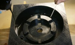
Then inserted the stator, with the phase wires on the upper side so that he bottom half of the stator going into the mold didn't have any wire channels to worry about...
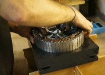
It was a pretty snug fit, so we needed to use a proper press to get the stator all the way snug on the bottom of the mold..
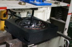
Then we used tape and plastecine to damn the inside of the top half of the core and seal where the phase wires come out, and continued pouring resin in from above. Even with the thick viscosity of this thermally filled resin, it seemed to have little problem navigating down between all the copper wires and stator teeth and really saturating/filling the whole thing by just sitting for an hour with no vacuum degassing or anything like that.
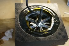
After an overnight oven assisted cure, things looked pretty good for our moment of truth. The stator came out of the mold with just the slightest effort on the press and looked glorious..
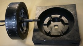
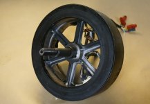
We've got it now installed back in the motor shell and ready for testing to see what effect this has on thermal results, but are currently all out of the ferrofluid samples and are waiting on the big batch to arrive in order to continue the tests.
One thing I realized when I had the MXUS motor apart is that the thermistor we had installed was glued touching both the winding and the core, and so would be showing an average temperature of sorts rather than the pure copper temperature. I think to better discern the effects of potting vs. not potting we'll want to repeat some of those experiments with one probe embedded only in the copper, while the other temperature sensors is only on the stator laminations.
flathill said:
try testing with the magnets on the side covers without fluid to check for eddy current heating of the windings.
For sure, this was one of my main concerns. I think it won't be too bad for this application of cooling the end turns in a DD motor since the steel core that the magnets are moving past is laminated to reduce eddies, but the other area of usage that intrigues me a lot is to use small pockets of contained FF to help shed the heat out of geared motors. In a geared hub, just putting FF in the air gap won't do wonders because the rotor is still has an additional air gap to get to the motor shell. But if we could find a way to have small magnets in the motor shell that support a FF thermal wiper to pull the heat off the rotor without inducing too many eddy currents in the metal, then that could prove fruitful.
there also may be an optimal orientation, not alternating like the rotor mags, but one south ring and one north ring that will form a ring of fluid. really interested to know if the fluid stays in place at high speed on the side walls or will migrate due the electromagnets back to the stator/rotor gap
Yeah, when I have the fluids I will run some experiments, but my hope is that you could design the internal geometry such that if the FF gets flung off the side plate magnetic support, that it would reconnect with it later and not wind up in the air gap space. Or if it does wind up in the air gap, that it gets pushed out (as we saw happened in my first test when the side plates weren't sealed) and then drawn up by the side cover mag. structure. This could all be a moot discussions because we might find from doing the potted core test that there are little extra gains to be had versus just a small amount of FF on the airgap and that's it, so we'll see.
spinningmagnets said:
ot only is this ferro-fluid heat-bridging a completely new thing that has unexpectedly come out of left field (at a time when most ebikers have not even heard of ventilating or oil-cooling yet), you are running pure research, and publishing the raw data.
Thanks. What's awesome is that this came pretty much out of left field for me too directly as a result of ES. I've been familiar with FF's for quite a while but it wasn't till Fetcher made mention in this thread here that it clicked how insanely ideal this could be as a thermal heat flow solution for direct drive motors. So yes here's to sharing ideas and results, and I'm glad to be able to contribute back with the tools and motivation to validate some of these concepts that others have experimented with.
What's really staggering (and kinda sad) is just how little R&D of any kind at all goes on at these giant factories and overseas companies that turn out ebike motors and other parts by the millions. It's all about moving the most amount of products with the least expense. There is collectively way more research and experimentation done by amateurs here on ES than all the ebike companies I've ever visited combined.


