Adaptto Mini-E/Max-E Owner's Thread

Cowardlyduck said:
Initially Boost was the same and current dropped around 50-55kph, so then I thought I would try OVS, since it seemed my issues were resolved. OVS 3 did get me up to 65kph before I ran out of road, but then I turned it back off as I don't need that kind of speed.
However now, even with OVS back to 0, Boost mode just keeps pulling and drawing more current. :?
First it worked, but after activate and deactivating OVS, it than doesn't anymore :?:
looks like there lies the problem and in my case it's very similar. It seems like OVS is always maximum in BOOST mode, despite that it is set to 0. the NORMAL mode works well (at least i think it does).
Anyway, on the same ride I got a bad pinch flat in the rear that destroyed my tube and tire. I only just ordered more earlier today, so won't be doing any more testing/tuning for a while. :(
sorry to hear that.
during my last ride i think catched the bad cold i have now, so i also won't do any testing at the moment.

sn0wchyld, big thanks for your input. If i'm up and about, i will try out your suggestions with the bike on the road. an oscilloscope i don't have unfortunately.
Also looking forward to see further findings from you.
 
Hello everybody,
I would like to discuss the autodetection feature of the adaptto controllers.
I only used it with a cromotor V3 9KV but with 2 different max e and 2 different firmwares. My experience is that it does not work all the time.
I had these different scenarios:
1. Motor rotates fine during the slow motion process and when entering the faster speed then the motor makes crazy forward backward movements and I had to release the throttle.
2. Everything slow and fast movement seems to work fine with one exemption: current was 6A at 80V. Then the display showed successful. After saving the changes and then turning the throttle the wheel turns in the wrong/backword direction.
3. Everything worked fine (current around 1A).

Next thing is how can I avoid the autodetection process in the future for this exact motor. Can I note all parameters and enter them manually or are there some hidden values saved during autodetection? This is something I would like to do when I only change the firmware. My backwheel with this cheap 50Euro trial motorcycle tyre can not be balanced perfectly and it is really dangerous to do the autodetection with high voltage batteries and therefor high rpm.
I used a 48V battery which was less dangerous because of lower rpm. Does this result in wrong autodetection parameters?

What are your experiences with autodetection and can anybody answer my questions?
 
My Cro V3 does exactly the same with both Mini-E's I have, unfortunately.. So far the best way I've found round this is to do the 'quick autodetect', which just gets the phase/halls sequence correct and then just manually adjust the settings. As you've said, note down the parameters for your settings and once you've set it sweet don't bother tinkering with Autodetect again as it'll balls it up.

Just for your info my settings are:

Controller Setup:
Calibration - Int Sensor: KTY83
Regen Settings - Smooth = Yes // Torque Rise = 0112 // Min SPD = 003
Advanced - Angle Corr. = -4.88 // Angle Corr2 = -1.40 // IND Timing = 0465us // Power timing = +1.40 // Power Timing2 = +1.40 // Wire R, mOhm = 094 // Motor KV = 6636 // Wire R PHC = Yes

Use the 'Manual Motor Tuning' section of the Adaptto Manual to fine tune these settings. This'll give you a rough point to start from. Also, as a hint for the IND timing section, use the speed limiter when finding the 'Cruise 'D' rating. I think it was 73-75kph for 'D' to appear on the debug screen. My phase wires are about 1.2m long so adjust to suit. You can change the wheel direction in 'Controller Setup - Direction = -/+'.
 
angle corr 2 and pwr timing 2 are only for the if you have a slave controller,2wd i thought :?:

i have cro 9kv also, I found the best setting so far to be:

angle cor =+1.2
ind +590us
pwr+1.4
 
Thanks guys for fast response.

@ridethelightning:
angle corr 2 and pwr timing 2 are for active regen and reverse.
If you have a slave controller it gets its own settings (info from somewhere in this forum).

@ccmdr:
good idea setting the speed limit to cruise speed to finetune IND timing.
What is a"quick autodetect" exactly? I guess testing in which direction the wheel
turns when pushing the throttle and then change "direction" or cables if necessary.

My first adapto max e has too high voltage drops (8V) during acceleration. Another forum
member has that too (20V). Who has that problem also? My second max e and my Infineon controller
have only 3V voltage drops.

Is it likely that a wrong autodetection can result in that high voltage drops?
Settings are:
angle cor =+0.51
ind +526us
pwr+1.4
which should not be very wrong. My question is and was: Are there any hidden parameters with
autodetection? Is it possible to get the adaptto to work perfectly without any autodetection?
 
A 2 channel oscilloscope should do it, depending on what failsafes the controller has (ie preventing output if no motor sensed). I'll do it later this week if no one else gets a chance before then.
basically you disconnect the phases from the motor, and hook 2 of these up to 1 channel of the oscilloscope (leave halls connected to controller).
take the corresponding 2 phase wires from the motor and hook that up to the 2nd channel
then you need something that can spin the motor up and hold it at near max rpm, ie another motor
spin the motor up and you will be able to see the difference (if any) between the 2 signals (one from the motor and one from the controller) when the throttle is pushed.

should make tuning pretty easy, low speed to get the hall offset spot on, and then adjust near max rpm to get the ind timing spot on. unfortunately its not going to be the same for every motor, and possibly not even every controller. so if you dont have an osiliscope and a 2nd motor that can spin the 1st motor at a stable rpm... it might be a bit of a tough one.
this is really exciting info!
it would be great to actually see the motor and controller waveforms in tuning. im thinking i could spin up the wheel by using another bike in contact with it, like friction drive.
 
Xantho said:
Thanks guys for fast response.

@ridethelightning:
angle corr 2 and pwr timing 2 are for recuperation.
If you have a slave controller it gets its own settings (info from somewhere in this forum).
that explains it then. i was thinking that also but someone had the wrong info there somewhere...
could you please clarify, what do you mean by"recuperation"?
perhaps thats like fine-tuning?
 
@ridethelightning
recuperation is charging your battery by breaking with the motor. Getting energy back instead of wasting it in heat.
 
Once again guys, angl corr2 is for active regen and for going in reverse.
Rest of the questions haves been covered several times in here. But yes, the thread is huge so it could be hard to find unless you read through everything.
 
Xantho - Can't remember exactly where the info is for the 'Quick Autodetect', but basically its as you say, just run 'Autodetect' until the motor is rotating and then quit out of it. i.e Run 'Autodetect' - Wait 10 Seconds until motor slowly rotates in a constant direction - Release throttle.

All it does is setup the phase and halls to rotate the motor in a direction (no need to disconnect the phase or hall wires for the 36 possible combinations). Make sure you change the 'Direction' (+ or -) so the wheel is pushing the bike in a FWD motion before modifying any 'Regen' or 'Advanced' settings.

Oh, it was a russian website that needed to be translated that had a really nice simple layout and noddy guide for all the settings. Can't for the life of me find it now, but someone will know what I'm on about :wink:.

I don't have knowledge on the vdroop issue, but as you've noticed already if it's incorrectly setup the controller uses more Amps and heats up considerably, more of an issue with constant high power usage on Mini-E.
 
Xantho said:
@ridethelightning
recuperation is charging your battery by breaking with the motor. Getting energy back instead of wasting it in heat.

keep in mind that there is normal regen and active regen. normal regen will ONLY put energy back into the battery, but when active regen enabled, the controller will apply current in the reverse direction below a given speed (around 10kmh)

it would be interesting for what kind of regen the values are considered (normal, active, and forced active), and how to find out the optimal settings.

maybe the opposite direction?
for instance anglecorr1 = 4° and anglecorr2 than -4°
 
madin88 said:
Xantho said:
@ridethelightning
recuperation is charging your battery by breaking with the motor. Getting energy back instead of wasting it in heat.

keep in mind that there is normal regen and active regen. normal regen will ONLY put energy back into the battery, but when active regen enabled, the controller will apply current in the reverse direction below a given speed (around 10kmh)

it would be interesting for what kind of regen the values are considered (normal, active, and forced active), and how to find out the optimal settings.

maybe the opposite direction?
for instance anglecorr1 = 4° and anglecorr2 than -4°

i think i will only tinker with that when i get all the other settings sorted first :mrgreen:
nice feature to get engine braking below 10kph, in the normal dead spot where i usually have to use the discs though..
 
Hello all, I think this is my first post here :) I've read the entire thread (yes, all 105+ pages) and I don't recall seeing this question asked.

I'm designing my battery system for the Adaptto Max-E and have a question re: the BMS cards.

The base BMS package comes with 7 balancing boards that can each do 4s. Is there a maximum for how many you can link in after the 7? I'm asking because minimally, I"ll need 8 boards for a 16s2P @ 59.2v BUT.. I'd REALLY like to do 20s2p @ 88.8v with 12 balancing boards total.

Can do?
 
HamsterPower said:
Hello all, I think this is my first post here :) I've read the entire thread (yes, all 105+ pages) and I don't recall seeing this question asked.

I'm designing my battery system for the Adaptto Max-E and have a question re: the BMS cards.

The base BMS package comes with 7 balancing boards that can each do 4s. Is there a maximum for how many you can link in after the 7? I'm asking because minimally, I"ll need 8 boards for a 16s2P @ 59.2v BUT.. I'd REALLY like to do 20s2p @ 88.8v with 12 balancing boards total.

Can do?

No need - regardless of how many parallel cells you have, the per cell voltage will be the same - you require only 20 or 22 (your cell numbers and voltages don't line up)
 
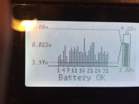
I have 3 additional cards and used the Adaptto just to monitor my 33s pack. Don't worry, I charged to 4.1v per cell for a 135v controller (150v FETs) and only sent 70v or so to the Adaptto Mini-E. Unfortunately only 32s can be displayed in the bar graph. I was able to see all 33 cells in the text read out. It looks like at least 40s can fit on the screen but the controller is limited on memory so they can't add anymore bars. Hopefully they will change this in the future.

Just a note to anyone who is adding more cards. I read the whole thread but I might be the first one to have added a new card in the US as no one else had this problem?

The new cards need to be configured as #8,#9,#10. Otherwise one the #5,#6,#7 cards won't work as the there will be duplicates. (The BMS sees the true #5 card but #9 is also configured as #5 which creates a problem.) The funny thing is that when you unplug the #5 card then the bars all of the sudden show up on the BMS for #5 but it is just showing card #9 which is configured as #5.

32s BMS picture:
32s adaptto BMS.JPG
 
First, I'd like to thank Offroader for his PM.

Let's assume I'm using these HK packs (http://tinyurl.com/jdjjf4c) , each of which is 4s and has a 5 wire JST that is pin for pin compatible with a balance board.
Here's my understanding of how the 16s2p battery setup would look:
Series1: 14.8v [battery pack #1] + 14.8v [#2] + 14.8v [#3] + 14.8v [#4] = 59.2v 20Ah (16s) ----\
Parallel Join: ~~~~~~~~~~~~~~~~~~~~~~~~~~~~~~~~~~~~~~~~~~~~~~~~~~~~~~~~~~~~~~~. . . > (16s2p) 59.2v 40Ah
Series2: 14.8v [battery pack #5] + 14.8v [#6] + 14.8v [#7] + 14.8v [#8] = 59.2v 20Ah (16s) ----/

So, if I wanted to monitor at each pack, that'd be 8 balancing boards total and just one more than what Adaptto sells as-is (4 boards hard with 3 that can be broken off).

Offroader recommended a 4 board count. I envision that would mean that battery packs #1&5, 2&6, 3&7, and 4&8 would each have a JST Y connector to a single board. But then, I'd lose monitoring at the pack level. With these HK RC foil packs, not having one balance board per pack is not something I'm comfortable with (yet).

@Scott I'd think Adaptto would have the screen in your 32s BMS picture as a summary screen. One could easily fit a LOT more info in on that screen by removing white space (e.g. white lines between the bars). That'd mean it'd be good for a quick look but you'd have to go elsewhere for details (which it appears you already can).
 
HamsterPower said:
First, I'd like to thank Offroader for his PM.

Let's assume I'm using these HK packs (http://tinyurl.com/jdjjf4c) , each of which is 4s and has a 5 wire JST that is pin for pin compatible with a balance board.
Here's my understanding of how the 16s2p battery setup would look:
Series1: 14.8v [battery pack #1] + 14.8v [#2] + 14.8v [#3] + 14.8v [#4] = 59.2v 20Ah (16s) ----\
Parallel Join: ~~~~~~~~~~~~~~~~~~~~~~~~~~~~~~~~~~~~~~~~~~~~~~~~~~~~~~~~~~~~~~~. . . > (16s2p) 59.2v 40Ah
Series2: 14.8v [battery pack #5] + 14.8v [#6] + 14.8v [#7] + 14.8v [#8] = 59.2v 20Ah (16s) ----/

So, if I wanted to monitor at each pack, that'd be 8 balancing boards total and just one more than what Adaptto sells as-is (4 boards hard with 3 that can be broken off).

Offroader recommended a 4 board count. I envision that would mean that battery packs #1&5, 2&6, 3&7, and 4&8 would each have a JST Y connector to a single board. But then, I'd lose monitoring at the pack level. With these HK RC foil packs, not having one balance board per pack is not something I comfortable with (yet).

@Scott I'd think Adaptto would have the screen in your 32s BMS picture as a summary screen. One could easily fit a LOT more info in on that screen by removing white space (e.g. white lines between the bars). That'd mean it'd be good for a quick look but you'd have to go elsewhere for details (which it appears you already can).

with 4 boards and the jst y connector, you're still balancing each cell. unless you really, really want to know what each individual cell is doing then there's very little point in having 1 balance board per pack. i dont think anyone uses cell-level BMS's, not even companies like tesla afaik. Is there a reason why you do want this? there's no real benefit, and is more expense (though in your case, it isn't too bad...)
 
sn0wchyld said:
with 4 boards and the jst y connector, you're still balancing each cell. unless you really, really want to know what each individual cell is doing then there's very little point in having 1 balance board per pack. i dont think anyone uses cell-level BMS's, not even companies like tesla afaik. Is there a reason why you do want this? there's no real benefit, and is more expense (though in your case, it isn't too bad...)

The benefit I see with 1 balancer per pack is that I expect to have pack issues over the term and would rather not have to pull two packs to troubleshoot which of the two it might be. Although I have no experience here (this is my first bike system), having 1 board per pack would allow me to see which pack is not performing and allow me to deal with that one pack, would it not?
 
I would say too much trouble if it is even possible hooking up each individual pack to the BMS. I guess an added benefit of doing it like that would be to know all your packs are hooked up and you haven't lost a connection to one of the packs.

If you have any issues with a pack you simply pull the two packs out, run them individually in a hobby charger and you will be able to easily determine which pack has trouble. Much easier to do that the very few times if any you will notice something wrong with a pack. Adds maybe an extra few minutes then pulling a single pack.

The best thing you can do to not have pack issues is to make sure the packs are not getting squeezed or moving around as that has caused almost all of my pack issues.

I have 7 packs hooked up together in parallel, and with 7 packs I have no problems noticing once a cell is going bad.
 
HamsterPower said:
sn0wchyld said:
with 4 boards and the jst y connector, you're still balancing each cell. unless you really, really want to know what each individual cell is doing then there's very little point in having 1 balance board per pack. i dont think anyone uses cell-level BMS's, not even companies like tesla afaik. Is there a reason why you do want this? there's no real benefit, and is more expense (though in your case, it isn't too bad...)

The benefit I see with 1 balancer per pack is that I expect to have pack issues over the term and would rather not have to pull two packs to troubleshoot which of the two it might be. Although I have no experience here (this is my first bike system), having 1 board per pack would allow me to see which pack is not performing and allow me to deal with that one pack, would it not?

You'll usually be able to see if you've got a dud cell, regardless of the paralleling (unless it's dozens of cells, might be a bit hard then). There's some value in what you're proposing, just (imo) its borderline worth it. With a 16x2 pack, its not hard to wire up cell level BMS's, and doesn't cost much more, so not a bad option to consider. Wiring could be easier too, as you stated you can have two completely separate 16s packs other than the +- end terminals, which might make placing the pack on the bike frame easier (ie, each group of 4 packs in series could sit on either side of the down-tube, or in 2 completely different spots). I considered it for my 20s 3p pack, but the extra cost (and display incompatibility) wasn't worth it. for you, its a bit of a different story.

By all means, go for it if you want to. its only another $13 or so, so hardly a big cost, makes wiring potentially simpler (Y cables can be hard to get neat and tidy too) and allows for cell-level monitoring. I'd still recommend vetting the packs before installing them either way (cycling them a couple of times on a charger to verify capacity/even cells, and then store them for a few weeks at storage charge to weed out any with high self discharge), but if i had a pack your size i'd probably have considered it too. I just dont think you'll see much benefit other than the (potential) flexibility of positioning the batteries on the bike.
 
Did someone experienced this behavior before?
img-20160106-wa0000yqpg0.jpg


The drift rises slowly, but constantly.
It took a month and 1800km to get me here from 0,009V after my first charge.
I Left the bike online for 48hrs but the drift only knows one direction.

The batt is 12 full cycles old.
20s19p Samsung 25r.

If its just one cell bank, i would say its my battery or my fault, but EVERY first bank of a 4 cell board?
The battery is spot welded, i did nothing special on these banks.......i did the same procedure for every cell bank.

I also have another minor issue, but it dosent bothers me too much.
My battery level is always 100%......but it was working in the beginning, i remember the first ride it was working, cause i remember i charged at 15%.
Now.....82V, 78V, 72V.....always 100% and my rem wh in the stats wont decrease also.
Maybe i changed something, when i played around with some settings, but i checked everything and dont know where to go.

img-20160106-wa0004bgs9s.jpg

img-20160106-wa0005rfxey.jpg
 
OK guys, slightly different problem this time.

Let's assume I'm using these HK packs (http://tinyurl.com/jdjjf4c) , each of which is 4s and has a 5 wire JST that is pin for pin compatible with a balance board.

Here's my understanding of how the 16s2p battery MAIN connection setup would look like (with their appropriate voltage and amp/hour figures):
Series1: 14.8v [battery pack #1] + 14.8v [#2] + 14.8v [#3] + 14.8v [#4] = 59.2v 20Ah (16s) ----\
Parallel Join: ~~~~~~~~~~~~~~~~~~~~~~~~~~~~~~~~~~~~~~~~~~~~~~~~~~~~~~~~~~~~~~~. . . > (16s2p) 59.2v 40Ah
Series2: 14.8v [battery pack #5] + 14.8v [#6] + 14.8v [#7] + 14.8v [#8] = 59.2v 20Ah (16s) ----/

Offroader recommended a 4 balance board count with JST Y connectors between packs #1&2, 3&4, 5&6, and 7&8. In other words, balancing in pairs along the series.

I envisioned battery packs #1&5, 2&6, 3&7, and 4&8 each connected with a JST Y connector to a balance board (still just 4 balance boards). In other words, balancing across the parallel pairs.

Also, I can't remember the details (it was a long 105 page read, this thread), but somewhere there was a discussion about someone blowing a controller due to unplugging the main but not unplugging the balancing boards. If I recall, it was in the 6C wiring area. And if I recall, the conclusion was that the simpler the wiring (if done right?), the less chance of an accidental plug separation or out of order disconnection blowing the controller.

Is there a right way? Is there a wrong way? Is one way better than the other? Does it matter?

REALLY wish Adaptto had a BMS guide.
 
If you use 6s or 5s packs, they have 6 and 7 pin JST connectors. Because the balance board is designed for 4s connectors you have to join wires together from the 5s or 6s connectors to work with the 4s connectors. So you will have a wire that is split between the two 4s connectors. Lots of issues here. If you accidentally don't plug things in right or unplug your batteries out of series you will short your BMS.

If you're using 4s batteries like the ones you linked, I believe how the packs are plugged in series does not matter when connected to the BMS, you can plug and unplug them any way you want, and change the series around without any issues.

I don't think I recommended you run the Y connectors between packs #1 &#2 in a series like you have shown as that would short out the battery. I recommended you have to take packs 1 & 2, wire them in parallel and then connect them with the Y connector for the JST-XH. Just a misunderstanding. Basically you need to rearrange how you have your packs connected in your description. But if you were to wire the packs each in their own BMS port you could leave it how you have it.

It was odd to run the packs in two sets of series like you were doing. If you were tun run them in two sets of series I guess you can connect them with a Y connector, but you would have to be careful of always making sure you connect them to the correct pack in the series.

Someone correct me if I'm wrong here. LOL

The reason you can even consider wiring each pack to the BMS is because those cells are so damn large. 20,000MAH per cell is real large cell and most people don't have close to that I believe.
 
Cowardlyduck said:
All these BMS problems and uncertainties.
I'm sure many have them working, but there's a reason myself and many others here refer to them as Battery Murdering Systems and choose not to use them.

Cheers

Yes, I actually never hooked my BMS up for my 6s packs. Just saw too many issues with wiring them in. My pack needed balance rarely and when it did it was usually because of a bad cell I had to replace anyway.

However, with my 18650 pack I'm building and will be using the 4s connectors, I'm going to use the BMS because it is much safer and easier.
 
Back
Top