APL's DIY axial-flux motor

APL said:
Too much drama the last few days, seems like everything is getting in the way of this project.
I'm overly familiar with this type of problem, wiht pretty much all fo my projects. :/

I had to look up 'Ostral',.. and still don't know what it means. :oops: But it looks Spanish, so maybe a religious thing?
It is a "religious thing", but it isn't Spanish. :lol:

First hit here:
https://www.google.com/search?q=Ostral-B

(this one in case it doesn't come up the same for you:
https://lexx.fandom.com/wiki/Ostral-B )


Reminds me of Orested though, a measurement of magnetism,.. Orested-B? :)
Do you mean "Oersted" ? ;)
https://en.wikipedia.org/wiki/Oersted


I've been racking my brain on how to mark them north and south, so I can keep things straight while bonding. Didn't want
to line them up on a table, because they could all jump together and break.

Then I realized that if I leave them all stacked together, they are the safest, and just flip over every other one.
Only have 20 minutes, so I need to figure out the fastest way to do it.
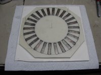
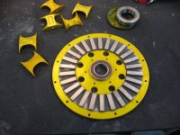
Compass?
 
Ah,.. I am enlightened, Ostral and Oersted. It's all wturber's fault. :lol:

Right larsb, I could do all the N, and then wait and do all the S. And use a compass to check, like amberwolf said.
That would save bonding times.

I'm dragging my feet on this a bit, but I don't want to go backwards,.. thats going to be difficult once they're glued. :!:

When the two rings are done, I hope I don't make the mistake of getting them stuck together.
56 magnet's times about 15 lbs of pull will be over 700 lbs of force to get back apart! :cry:
 
The only good thing about crapy weather, is that you get stuff done inside. :thumb:

I was able to get one side boded, and the waxed indexing form worked well, but didn't survive the removal well enough
to use over. Heres another place where a 3D printer would be awesome. I could print the spacers, and even leave them
bonded in place.

Bonded magnets.jpg

I might still fill in between the magnets with resin, to strengthen it further, and make it easier to clean off iron dust,
which seems to find it's way on to the magnets from everywhere.

Then a good coat of primer, to keep them from rusting,.. mount them, and I can finally move on to the stator wiring.

Rotor with Back Iron.jpg

After that, I won't have any excuses to drag this build out any farther,.. time to throw the switch!
 
About 1/8" or 3mm, but I've been sanding on them, so a slightly less. Magnets are 4mm.
 
That should be good. If you test with a paper clip on the back side and it sticks strongly, it means it's too thin.
 
No, theres hardly anything. I noticed that after I was done,.. that when I set it down on the metal shelf,
there was barley any stick on the back side. I thought it was odd.
The other side, of course, is just the opposite. I accidentally got it too close to the belt sander table, and it
snapped down hard! I had to 'slide' it off, and I could barely do it. :shock:
And that was only half the ring.

These things are dangerous!

I'm beginning to wonder if my thinned out aluminum rotors are going to be able to take it. I might have to double up
on the back iron mounting screws as well, and use nuts on the screws.

In hindsight, I should have just used all steel rotors,.. the aluminum just complicates things, and makes more work.
The motor would be thinner, stronger, and maybe even lighter.
 
APL said:
In hindsight, I should have just used all steel rotors,.. the aluminum just complicates things, and makes more work.
The motor would be thinner, stronger, and maybe even lighter.

Not sure if that'd be wise. 7005 t6 Aluminium is up to 25 to 30% lighter than any hard steel alloy; on top of that it goes much easier on tools like drill bits because of its softness, and finally, the best part is its corrosion resistance. Steel always ends up rusting in places you don t want, especially when there are moving parts. The only real alternative i d consider is going stainless but than you need really good machinery, in combination with extensive 3d printing to save time and weight. This guy did it for an instance
 
I just love that motor build. Unfortunately, he never finished it, or at least, not yet. Love that CNC!
I wish he would finish it, because I'd like to know how much torque it produces, since it's coreless.
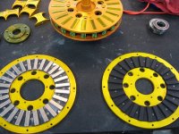
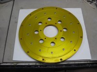
Your right about steel being harder to machine, my little lathe doesn't handle large disc's very well. But
I would only have to do the bearing hole, and the outside diameter. The rest is all weight saving holes.

The rotors would still be 1/8" steel. There would just be the added amount of material on the inner and
outer diameter of the back iron ring. And that would be filled with holes. So I think it would be at least the
same weight as adding the aluminum, if not lighter. If I switch to larger magnets, I'll probably try one and see.
Steel is cheap.

Not as sexy as aluminum fore sure, but the steel could be plated, or at least painted something sweet.
Or both.
 
APL said:
I just love that motor build. Unfortunately, he never finished it, or at least, not yet. Love that CNC!
I wish he would finish it, because I'd like to know how much torque it produces, since it's coreless.
Sure he did: http://build-its-inprogress.blogspot.com/2015/02/finishing-up-coreless-motor.html
 
Thanks qwerkus, I finally get to see it run! Funny, I thought it was a lot bigger than that. Looks like a real
hight speed unit.

Gives me hope,.. if this build spins even a fraction as smooth as his, I'll be delighted. :)
 
Finally coming to the end of the rotor thing. I have the other side bonded, and it's ready for alignment.

Rotor set.jpg

I decided to use 13 steel rivets to hold the back iron on,.. they can be removed, and replaced with bolts
if need be. Once I get the black panel painted on them, they won't be very visible.

Rotor Rivets.jpg

The alignment between the two sides is fairly easy,..with some foam board in between them, they self align,
and I can line up the rotors, and mark all four pieces.

Even with a 1/4" of foam board between them, they are still very hard to slide apart!


Now I can finally get the stator wiring finished, and start setting up the system,.. still have to make a test stand.
 
Looks beautiful.


But you should start thinking about another material to make the stator plates from. You will have massive eddy currents in the aluminum that will cause unacceptable drag. Slotting the ends will help, but there is enough area between the coils to be a problem.

The material needs to be non-conductive. Fiberglass board would be one possibility. Outside of the area swept by the magnets, it can be metal.
 
Yea, that is a potential problem, and a different material is the answer. Carbon fiber is conductive,
so I suppose thats out, although it's more like a resistor? Glassboard would be perfect, if it would be
strong enough, hard to say at this point.

Do you know if carbon fiber has eddy/induction traits?

The cores will protrude about 2mm on each side, once things get screwed down tight, and the air gap is
another 1mm,.. so 3mm from the magnets to the surface you are pointing at. I also have the option of ball
milling into that aluminum another 3mm. between the cores, at that distance,.. 6mm, induction shouldn't be
any problem.

Bottom line is,.. I'm just going to have to try this out and see what happens. As strong as these magnets
are, I'm fearful that none of this is going to work, unless all the forces balance out, and the stator and
rotors become magnetically neutral with each other. Thats the biggest worry I have at the moment.

Of course, I could be wrong. If I get it to spin, my laser thermometer will tell all! :)
 
Whether the aluminium stator works or not, it's an excellent project and has been fascinating to follow :bigthumb:
 
Carbon fiber is somewhat conductive, but not sure how it would do with eddy currents. It could be tested. Old school Garolite would be something to look at or stuff called G10, which is just like fiberglass circuit board material only thicker. Fiberglass is sort of rough on the machine tool bits and makes nasty dust. The linen/phenolic Garolite is easy to machine and does well at elevated temperatures but not quite as strong.

Another suggestion: make some threaded holes in the rotors just inside the magnet ring to help with assembly/disassembly. As you have found out, the forces from the magnets are extreme. With the threaded holes, place temporary bolts in the holes to keep the magnets away from the stator during assembly, Once in position, slowly unscrew the bolts a little at a time to gently get the rotor in position without crashing. To disassemble, bolts will force the rotor away from the stator far enough to pull it off by hand.
 
Or simple heat resistant plastic. Super easy to work with. Given the amount of material, it should be strong enough to hold the coils in place. You can even have it 3d printed somewhere to speed things up. But as he said: you put so much effort into this; better try it first as it is before trying to super optimize it.
Also, IRRC the goal was a fairly low rpm high torque 750w mid drive motor to be placed between the crank and the rear wheel. If rpm is low enough, eddies are definitely not the main issue.
 
There are so many versions of glassboard, Garolite, G10, F10, phenolic, etc., I made a list of over half a dozen.
And then theres plastics too, as qwerkus has mentioned. plexie, nylon, lexan, etc. Endless really.
Much to think about, and research.

I did think at one point,.. that it would be cool to come up with a design for an all 3D printed motor. Except
for the cores of course. Perhaps with a design similar to this one,..it may be possible. :?:
If coreless had enough torque, it would actually be easy to do.

I drilled some extra holes in the rotors to be threaded, like you said, for that reason. But I think I'm going to make
some custom 'spreaders' that fit in between the rotors and push against a larger area, as I'm afraid the screws might
warp the rotors. Maybe they won't, but I don't want to find out right away.
If I put some screws on both sides of the magnet rings, it may have a better chance, and be more even. I don't
really want to drill any more holes in the back iron itself, although, that would work the best.

I'm also going to place some 1mm thick plastic in the air gap area, when I put it together for the first time, that
can be pulled out, once it's assembled. Just to make sure that I get at least one test out of it before I muff it all
up somehow. :wink:
 
Keep the plates and save your work. Just cut slots and shim with epoxy or other insulator.
Not at the place where you have already tapped a set screw. Jigsaw an angle from one side
(perhaps the clockwise side) of each stator to the outer edge. So you will still have one solid
plate, but no shorted turns. Crescent or S shaped slots may improve the interlock. Fault lines
of unplanned disassembly won't easily slip by each other if they fit somewhat like a puzzle.
If you use a straight cut, perhaps slip-proof by drilling holes for pins. -------O--------O--------
 
Thanks KD5ZXG, I had thought of the slant cut, and that was going to be the plan, but I like your pin idea
better. I could come off the side of the slot somewhere, and up in an 'L' shape cut, and have plenty of room
for a pin,.. for a non slip cut. 1/8" to 1/4" hole, and pin. Easy to do.

Suggestions for a pin material? Metal is out, so..something hard, and non conductive. Fiberglass rod, nylon,
ceramic, standard glass rod, etc.

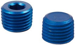
I suppose I could re-anodize, and use an anodized aluminum rod,.. anodizing has a non conductive surface.
 
You could buy anodized aluminium screws, would be an easy fix, easy to find in RC stores :D

Also note that the resistance can be very small and still stop the eddy currents - i found a science paper showing this for laminations, it's in a thread called "rotor losses" in my posts. With this in mind even black oxide grub screws might work.
 
Silicon nitride ceramic pins would do the job with no magnetic or conductive properties. I don't know how much that sort of thing costs, but they're listed on Alibaba.
 
Thanks larsb, anodized screws would work well, stay put, and are easy to get. A little epoxy and I'm sure
nothing would move. I'm thinking large anodized set screw. :thumb:
Chalo's ceramic pin idea is good as well,..I'm still looking, theres a lot of different offerings to go through.
I found some silicon ceramic roller bearings that would be nice. Don't know how available they are yet though.
Perhaps regular ceramic would suffice, theres tons of options there too.

Anodized plugs.jpg

View attachment 1
 
Back
Top