APL's DIY axial-flux motor

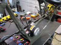
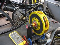
I remember my grandpa using that set up on the farm,..actually not to far off though, I think I'll use
the little scooter's motor, and a long chain to drive the cog on the 'Midas motor'.

I ordered a tachometer, and as soon as it gets here, I'll try to get a Kv. I tried to measure phase ohms,
but my meter isn't up for it, I can't really get anything definitive.

I was able to cut back the plastic insulator, center the stator, and give it another spin test, and noticed
that it definitely has a lot more drag than normal. Thought maybe it was the bearings, but after checking
them out, it's not. Feels like wading through a strong river current. Something magnetic.

Not good. Maybe your right about shorted turns, or aluminum eddy currents, but the other thing that
has always bothered me about this layout is the bottom side of the cores, and magnets, being so close
to each other. Theres really no separation there. On the top side theres plenty of separation.

My air gap is only .040" which could be a little too close? I can try spacing it out another millimeter, and
see what happens.
 
fechter said:
Another fun test is to short the phase wires and then turn it to see how strong the resistance is.

This would be also useful to find out saturation current.
If we short all three phase wires and measure the current between them while the motor get spun to higher and higher RPM.
Only problem is to find a gadget or drive train that is powerful and torquey enough :)
 
APL said:
I ordered a tachometer, and as soon as it gets here, I'll try to get a Kv. I tried to measure phase ohms,
but my meter isn't up for it, I can't really get anything definitive.

I was able to cut back the plastic insulator, center the stator, and give it another spin test, and noticed
that it definitely has a lot more drag than normal. Thought maybe it was the bearings, but after checking
them out, it's not. Feels like wading through a strong river current. Something magnetic.

Not good. Maybe your right about shorted turns, or aluminum eddy currents, but the other thing that
has always bothered me about this layout is the bottom side of the cores, and magnets, being so close
to each other. Theres really no separation there. On the top side theres plenty of separation.

My air gap is only .040" which could be a little too close? I can try spacing it out another millimeter, and
see what happens.

Regarding the phase to phase resistance you could lead a given current through two phases (by using a battery charger and charge a battery through the motor for instance) and then measure the voltage drop between those two phases and do the math.
The thing with the decreasing magnet coverage from inside to the outside is definitely not optimal! Was already mentioned.
An airgap of 0,040" (1mm) is already quite large for a motor this size and the wider you make it, the lower the magnetic field streght will and this could shift kV and kT to an area you do not want to have those numbers.
To me the motor looks like it has been made very accurate so maybe you can decrease it further.

Is there any wobble when the rotor is spinning?
 
larsb said:
If you short without load you'll likely burn the motor in no time. It will be like 0-x kW of heat into the windings.

An oven heater coil and a bucket of water would do the trick
Yes of course you would have to do this in steps with cool down time between.
Someting like:

5RPM -> measure current and write it down.
10RPM...
cool down
15RPM...
20RPM

and so on

Up to a given RPM the short circuit current will go up quite linear until core saturation takes place. This would make a nice curve where we could read off saturation current.
 
The laser tach that I ordered still isn't here, but should be today, so no Kv yet.

I finally got the test stand built, mounted the motor, and decided just to go for it, and hook it up to the power.
The first test was a bit disappointing, that is, it didn't just take off spinning, as I had hoped. :(

First Test.jpg


It did however, try to at least. It will move forward a few inches, sometimes half a turn,.. and then go back and
forth 1", as if it's searching for direction. Pushing it along by hand doesn't resolve this.
(Yes, I tried all the phase wiring combos)

I notice a clicking sound coming from the controller, which I assume is it's sensors trying to get a fix, as it fluctuates.
Then it shuts down after 5 - 10 seconds, but will start up again after the throttle is released.
I'm assuming this is normal as well.

The coils start to get warm after several test's, so I don't push it very hard, and give it time to cool.
Hmmm, it's time to put on the detective's hat, and figure this out.

One thought I had was to put the back iron rings back on the lathe, and shave the bottom half of the magnets off
in an attempt to get more magnetic separation, which may be confusing the controller.
Not right away of course, but if it made the difference, then I would know if it's the problem.

As a final resort, if this can't be resolved simply, I will go back and rebuild the stator plates out of fiber board, and
probably go to an 18 slot configuration, for more separation, and normal wiring, and move forward from there.
The coils are built already, and I can easily rewind if necessary.

But I'm probably getting ahead of myself with all that talk,.. any ideas on the next move?

Also, madin88, theres no wobble in the stator, it's surprisingly solid.
 
Do you have an osci or do you know someone so that you can measure BEMF?
With more magnet separation do you mean the gaps between the magnets, thus magnet coverage?
 
Not sure on the BEMF question, if you mean oscilloscope, I have an automotive one I haven't looked at in years,
perhaps I can use that.

Sorry, I mean the gaps between the cores, the inside diameter specifically. Limited knowledge on this, and
maybe on the wrong trail, but I assume the cores and PM's shouldn't overlap at all, as mine appears to do.
Looks like the magnets are slightly wider than the space between the cores on the inside. 1 -2 mm.
 
I dont think that matters, and think you should check for shorts in the wiring. Try to measure is the motor wires are somehow shorted to rotor iron (maybe a tight winding has damaged the insulation). The separate the three windings and measure their resistance to see if one is different fro the other 2

What you are talking about may drop efficiency by 1 or 2 %, but will not stop it from working.
 
That sounds reasonable. It does act as though it's shorted, and would explain why I can't get a decent ohm
reading, and why it doesn't turn any different wether I short the phase wires together or not.

One can only hope. That would make it simple. I'm probably not that lucky though. I'll tear it down and see
what I can see. I'll see if I can get some other readings first though. Kv, and BEMF.

I can also disconnect, or unwind all the cores,.. put it back together, and give it a spin, to see how that feels.
The comparison might tell us something. Might even rewind with 14 awg,.. something to think about.
 
FWIW, the ohm reading most likely will be in the milliohms, so unless you have a meter designed for that low a resistance, you won't read anything significant--a typical multimeter wont' have a clue it's not just basically a short circuit.

There are some cheap meter units I've found here and there, but almost all of them are clones of each other, and none of them will measure stuff this low (especially really low inductances). Found sites claiming they had super cheap meters that *would* do it, but the few that have pictures are either more of these same clones, or other stuff so similar that I doubt they could do it.

I wanted to measure the parameters of various motors I have around here so I could test them with the SFOC5 without jumping thru hoops over and over again repeatedly changing the SFOCs settings, hoping that evnetually I'd get the "right" settings, and that any wierd behavior I get is caused by the SFOC and not just wrong settings. :/

But so far I can only find measuring devices for very low resistance, and very low inductance, that are separate, and each rather expensive (for my budget, since I don't actually "need" them for any essential work). :(


I've been told there are methods for using other basic test equipment (current limited power supplies, voltmeters, oscilloscopes, etc) to measure stuff like this, but can't get those that say I can do it to tell me *how*. :roll:
 
My recommendation

https://endless-sphere.com/forums/viewtopic.php?f=30&t=46476&start=25#p698230

Scroll down to picture dsc01169

Basically this is the motor put together only halfway. Only one rotor plate with all the stator wiring accessible. The single rotor plate will still induce backemf in the stator when you spin it. Not as much as when the motor is proberly put together, but enough for measurements. In your setup, spin the rotor (drill ?) and measure all coils (AC voltmeter). Write down the voltage for each coil and proceed from there....
 
@amberwolf: I've been looking at the DER "de-5000" instrument:
https://www.deree.com.tw/de-5000-lcr-meter.html

Teardown:
https://www.eevblog.com/forum/testgear/der-ee-de-5000-unboxing-and-teardown/?all

seems worth it at about 100usd
 
Maybe, but that's way out of my budget range for "convenience and curiosity". The best I can hack is about a tenth of that cost for this purpose. (I don't expect to *accurately* measure at that kind of price, but it might get me "close enough" :lol:)

I'm also not sure it does resistance low enough to measure motors.
 
Thanks for the info. on ohm measurement's, I remember Doctorbass stating hi-end meters when he did his
5300 series tests. I imagine they use specific leads with plated ends as well.
https://endless-sphere.com/forums/viewtopic.php?f=16&t=19301

A theoretical ohm's is possible by taking the length of wire used and doing the math. 14 awg is 2.5 ohms per
1000 feet, mine is roughly 4 ft. x 21 divide by 3 for each phase. But,.. that doesn't help with diagnostics.
Hopefully, we can solve this motors problems without needing the info. If I had plans for doing lot's of motor
work, I could justify a meter purchase.
Madin88 had an idea for alternative ways to measure low ohm's if needed?

Lebowski, I was thinking of removing one back iron assembly from a rotor, and try running the motor that way,
to see if it makes a difference.
I can also do the coil tests like you recommend, but don't think I can spin a rotor with out full motor assembly.
Since the AC reading doesn't require large wire, I'm hoping I can run lots of enameled wires out the three phase
wire holes, I can wire one side of all the coils together.

I'll try to get a Kv while it's still together, then tear it down and inspect for shorts, and do a wiring check again.

Another thought I had, was to rewire it in series, like every other motor out there, and see what happens.
Probably not the most efficient, but just getting it to spin is more important at this point.
 
No, they're not wired in parallel. Perhaps I misunderstood you when you said to measure 'each' coils output.
To do that I would have to disconnect all the coils, and re-wire, running 22 wires out,.. for 21 coils.
My bad.

Perhaps you meant to measure each phase of coils together, as fechter just stated, which of course, I plan to do.
The laser tach. finally arrived today, so I can proceed with that. I'm working on getting the drive motor hooked
up at the moment.

Not sure what RPM I can achieve for an AC test. Any preference? 100rpm?
 
Absolutely stunning work, kudos!
I'm particularly impressed with the spacers, I wonder how you machined them. They look really beautiful.

Too bad it doesn't work just yet, but I'm sure you will figure it out soon.

I was wondering, aren't the aluminum plates on which are mounted the coils interract with the field? Aluminum isn't ferromagnetic of course, but it does interact with magnetic field change. Wonder how this could be (or not) an issue.
 
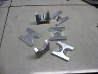
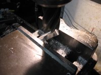
Thanks Dui, ni shuo de dui. Spacers are 1/2" flat stock, and I used a large end mill and just plunge cut
the pieces in the vice. Mostly eyeballed it, and massaged it as I went. A couple of chamfers on the tops,
and a bit of belt sanding. The only really precise cuts were the length of the spacers, which determines
air gaps.


Spacers 1.jpg

Spacer machine.jpg

Finished spacer..jpg

The motor is a beautiful piece of sculpture at the moment, and would spiff up any shelf,..but with all the
brainpower we have here, I'm not worried, we will prevail!

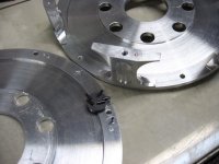
The aluminum stator plates are indeed a possible culprit, and have been discussed several times. As we dive
into this mystery, the plan is at some point, to cut the plates at each magnet and break the loops.
If that makes a difference, then I will remake them out of something nonferrous, such as glass board.
Stay tuned, and thanks for following! :)
 
OK, so I finally have some data on the AC output. I hooked up the little scooter motor to do the
spinning, and it complained quite a bit, but growled away enough to get some readings.

AC test.jpg

It was easier to run it up to a certain volt out, rather than start from an RPM. This meter has an
annoying lag time before it reads out, and trying to hold the throttle steady for any length of
time is difficult.

I took several readings, and the RPM fluctuates plus or minus 5 rpm, but basically this is what I got:

YG- .50v at 135rpm.
YB- .50v at 153rpm.
GB- .50v at 154rpm.

I took a temp reading before I started at 70 degrees, and after 3 - 4 times, 5 - 10 minutes it was 82 - 86 degrees.
The stator, coils, and axle were warm, but the rotors were cold.

OK. so then I finally checked for a short to the case, and sure enough ,.. it was shorted on all three. :oops:
Don't know why I didn't check that in the beginning,.. I'm claiming 'old age'. :)

Anyway, a short doesn't mean anything by itself, as no part of the circuit is connected to it.
But, if theres more than one, then we have a problem.

At any rate, a tear down is in order to see just whats touching what, and where.
 
APL said:
Thanks Dui, ni shuo de dui. Spacers are 1/2" flat stock, and I used a large end mill and just plunge cut
the pieces in the vice. Mostly eyeballed it, and massaged it as I went. A couple of chamfers on the tops,
and a bit of belt sanding. The only really precise cuts were the length of the spacers, which determines
air gaps.

Very nice craftsmanship, love it.

APL said:
The aluminum stator plates are indeed a possible culprit, and have been discussed several times. As we dive
into this mystery, the plan is at some point, to cut the plates at each magnet and break the loops.
If that makes a difference, then I will remake them out of something nonferrous, such as glass board.

Now that I think about it, I actually doubt that was the issue. At least it shouldn't be the cause of it not being able to move at low speeds. Reason being that at such speeds the fields are not changing very fast, if there were any issue they would be more likely to occur at higher speeds (at least I think so).

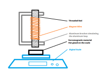
Instead of ruining your beautiful plate, I suggest you to do this basic test:
coil test.png

Basically simulate what is going on, comparing two brackets loops: one made out of aluminum, and an other one made of plastic.
See if there is any difference regarding the pulling or pushing force and if there is any significant change in coils and brackets heat. You could maybe test several materials this way and even see how it behaves with a variable signal.

It will take you very little time to do and it might avoid you some tiresome work, especially since I don't really see how you could cut the loops while keeping the little screws that hold the coils tighly in place.


APL said:
OK. so then I finally checked for a short to the case, and sure enough ,.. it was shorted on all three. :oops:
Don't know why I didn't check that in the beginning,.. I'm claiming 'old age'. :)

Well that's pretty good news!
Now time to find it! Hurry, we want to see this beast running!!
 
Back
Top