I wouldn't trust anodizing to stay non-conductive. It's not very thick. There are lots of ways to insulate a screw. Look at any big transistors with heat sinks. Most use a plastic washer of some type. But I think that even if the loops are cut, there will be enough area of aluminum between the coils to create a major eddy current. All this will be immediately evident when you assemble the rotors and try to spin it by hand.
You are using an out of date browser. It may not display this or other websites correctly.
You should upgrade or use an alternative browser.
You should upgrade or use an alternative browser.
APL's DIY axial-flux motor
- Thread starter APL
- Start date
If you're curious, you can take a good magnet, and a sheet of aluminum stock, and just use your hand to quickly swipe the magnet across the surface. You will probably be able to feel the resistance of the magnet pulling against the eddy currents being generated in the metal.
APL
100 kW
- Joined
- Aug 6, 2018
- Messages
- 1,113
Well thats kind of my point,.. it isn't very much resistance, I've done it many times. And, if you put a piece
of cardboard in between them, it cuts it in half, or by a large amount. I'm thinking that there will be 3 - 4mm
distance from the magnets to the surface of the aluminum stator plate.
I don't expect much induction at that distance, but there are 52 magnets, and 300 to 600 Rpm, so I could be wrong
about all this. Recon were going to find out pretty soon!
I don't actually expect much of an issue...but it will still be interesting to see. 
If you are curious, you can take a laser thermometer, and keep it pointed at the edge of one of the coil plates, then spin the motor using another motor, at the same RPM it's expected to run at. A temperature rise would indicate if there is a problem to be fixed, or even worried about.
Just remember--quite a few of us look for potential problems even where they may not exist...I think our brains must be wired to look for fun this way or something. :lol:
APL
100 kW
- Joined
- Aug 6, 2018
- Messages
- 1,113
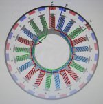
Time to wire this thing up! Here's the schematic for the 21/26P set up,.. the way they have it balanced out
is a bit odd, but I'm thankful that it's been figured out for me, because I would have just wired it in series, and
who knows what that would have done.
I bought some 10 gauge marine wire, and shoved it through the axle with room to spare. I could have used some
larger and better wire, but don't expect to be using that much power any time soon. I'll use some colored shrink
wrap to designate the phase colors, once they're figured out.
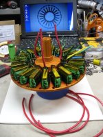
Fired up the solder pot, and tried it out on the multi strand enamel. It doesn't just fall off,.. you have to
wire brush it a little bit, and it takes several dips, but it's still better than a solder gun.
View attachment 1
Makes enough smoke to choke a cow! So if anybody try's this, make sure theres lots of ventilation. I think I'm
just going to move it outside, because I have lots of wires to tin.
is a bit odd, but I'm thankful that it's been figured out for me, because I would have just wired it in series, and
who knows what that would have done.

I bought some 10 gauge marine wire, and shoved it through the axle with room to spare. I could have used some
larger and better wire, but don't expect to be using that much power any time soon. I'll use some colored shrink
wrap to designate the phase colors, once they're figured out.

Fired up the solder pot, and tried it out on the multi strand enamel. It doesn't just fall off,.. you have to
wire brush it a little bit, and it takes several dips, but it's still better than a solder gun.
View attachment 1
Makes enough smoke to choke a cow! So if anybody try's this, make sure theres lots of ventilation. I think I'm
just going to move it outside, because I have lots of wires to tin.
That sure is an unusual wiring pattern, but looks right. If you get a coil reversed, it will cause a serious drag. If not too hard, the wye connection point should be located where you can disconnect them easily. You could also experiment with delta vs. wye.
Another fun test is to short the 3 phase wires and spin the motor by hand to see how strong the resistance is. A good motor gets very hard to turn with the phases shorted.
Another fun test is to short the 3 phase wires and spin the motor by hand to see how strong the resistance is. A good motor gets very hard to turn with the phases shorted.
APL
100 kW
- Joined
- Aug 6, 2018
- Messages
- 1,113
To bad it's such a brain boggler to figure out how to switch between delta and wye on the fly. It would be
like having a two speed motor. I know it's been done, but I think I'd have to drill some more phase wire
holes in the axle.
Not that I 'need' a two speed motor,.. but I know others have a need for speed. 8)
I'm thinking that it wouldn't be all that hard to pop the stator plate off and switch the wires, to experiment.
It's also possible to run the phase connections out between the coils, for access from the out side, after
the motors put together.
APL
100 kW
- Joined
- Aug 6, 2018
- Messages
- 1,113
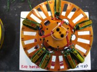
Heres how the first phase lines up. I figure I better do a dry run, and get everything installed and sized,
before I solder anything. Not a lot of room in there for all the coil wires, so it's probably going to get ratty
no mater what I do.
I'll add more shrink tube just before I solder it all up, to keep the wires from rubbing on anything.
Red numbers are reversed cores. None of it makes any since to me, so I've got my fingers crossed on this one.

larsb
1 MW
There's a mistake at 10,13,14?
Every tooth in one phase changes direction on the scheme except where the 7 coils variation meet between 10&13
Every tooth in one phase changes direction on the scheme except where the 7 coils variation meet between 10&13
APL
100 kW
- Joined
- Aug 6, 2018
- Messages
- 1,113
OK, one more stator photo before I take it apart to solder, and then button it up for final assembly.
Now I can see a pattern of three black, and four red, that wasn't very obvious before. Gives me confidence
that I'm getting it right.
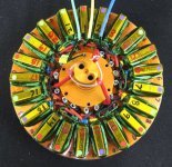
It's getting pretty ratty in there, so things are hard to see now, but the wiring pattern seems to repeat itself
consistently, which is good.
I think I'll escape this part of the build unscathed,.. but I'm a little worried that the power of the magnets may
pull, and warp the thin stator plates inward when I put it together. Losing the air gap.
If I get past that potential problem, then it should be home free for a test run.
Now I can see a pattern of three black, and four red, that wasn't very obvious before. Gives me confidence
that I'm getting it right.

It's getting pretty ratty in there, so things are hard to see now, but the wiring pattern seems to repeat itself
consistently, which is good.
I think I'll escape this part of the build unscathed,.. but I'm a little worried that the power of the magnets may
pull, and warp the thin stator plates inward when I put it together. Losing the air gap.
If I get past that potential problem, then it should be home free for a test run.
APL
100 kW
- Joined
- Aug 6, 2018
- Messages
- 1,113
Kind of a progress report, although there hasn't been a lot of progress. 
The enamel didn't come off using the solder pot as easily as I had originaly thought,.. turned out to be
a lot of work, so I reverted back to the old way of using paint stripper instead.
It works a lot better, but still a bit messy, and a lot of rinsing afterwards, I'll just use the solder pot for
the tinning.
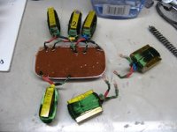
At any rate, I should get it soldered up in the next few days, and move on to the assembly part, which
has it's own list of problems to address. Aligning all the cores with the set screws, and spacing the air gap
with plastic 'pie' pieces that can be removed after assembly.
Anyway, things are happening, although a little slower,.. due to the 'clash of summer projects and events'.
The enamel didn't come off using the solder pot as easily as I had originaly thought,.. turned out to be
a lot of work, so I reverted back to the old way of using paint stripper instead.
It works a lot better, but still a bit messy, and a lot of rinsing afterwards, I'll just use the solder pot for
the tinning.

At any rate, I should get it soldered up in the next few days, and move on to the assembly part, which
has it's own list of problems to address. Aligning all the cores with the set screws, and spacing the air gap
with plastic 'pie' pieces that can be removed after assembly.
Anyway, things are happening, although a little slower,.. due to the 'clash of summer projects and events'.
APL
100 kW
- Joined
- Aug 6, 2018
- Messages
- 1,113
Stator is finally all soldered up. I cut down some crimp connectors, to solder all the coil wires together with, so they're
put together well. I could have shortened up all the wires, but stripping enamel is a pain, and you never know what
changes you might have to make. Best to have a little extra.
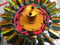
I installed all the set screws, and locked down the cores. At the moment I'm in the process of centering the cores
as best I can.
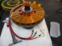
I should have the rotors mounted in a few days, and we can finally see what it looks like completely together.
put together well. I could have shortened up all the wires, but stripping enamel is a pain, and you never know what
changes you might have to make. Best to have a little extra.

I installed all the set screws, and locked down the cores. At the moment I'm in the process of centering the cores
as best I can.

I should have the rotors mounted in a few days, and we can finally see what it looks like completely together.
APL
100 kW
- Joined
- Aug 6, 2018
- Messages
- 1,113
Update! 
Finally got this this beast together, and the good news is, it turns,.. by hand. :thumb:
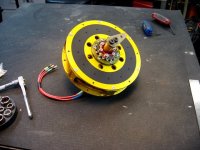
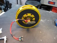
A big load off my chest, although there are some problems to solve yet. The air gaps are a little uneven,
but I can shim the bearing caps/bearings, to center the stator. And the plastic insulator rings I made for the
cores are rubbing on the spacers. No biggie, I can cut them back,.. but it won't be pretty. They're clear, so
it won't show to much.
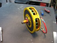
Even with the rubbing, when I turn it by hand, it feels like any other DD motor I've turned, a good strong
magnetic feel, not too much,.. not too little. I'm pumped!
Starting to think it might have a good chance at running. 8)
Time to build a test stand.
Finally got this this beast together, and the good news is, it turns,.. by hand. :thumb:


A big load off my chest, although there are some problems to solve yet. The air gaps are a little uneven,
but I can shim the bearing caps/bearings, to center the stator. And the plastic insulator rings I made for the
cores are rubbing on the spacers. No biggie, I can cut them back,.. but it won't be pretty. They're clear, so
it won't show to much.

Even with the rubbing, when I turn it by hand, it feels like any other DD motor I've turned, a good strong
magnetic feel, not too much,.. not too little. I'm pumped!
Starting to think it might have a good chance at running. 8)
Time to build a test stand.
wturber
1 MW
Well, I'm betting it will run. Whether it will run well with the power and torque you want is another story. But I've got my fingers crossed.
Lebowski
10 MW
Did you check, for each phase, the bemf voltage of the 7 coils in series ? Is it roughly 7 times the voltage of 1 ?
Putting mine together, got my fingers squashed a few times as the rotor halves really attract each other...
Putting mine together, got my fingers squashed a few times as the rotor halves really attract each other...
APL
100 kW
- Joined
- Aug 6, 2018
- Messages
- 1,113
Thanks for the thumbs up guys, just as soon as I can resolve some issues, and get the test stand built,
I'll give it the juice.
I'll start out by using my E-cruiser phase wire hook up, since I know that system works, and will eliminate
any problems from that end. The test stand will just be some angle iron and 'C' clamps, to make it easy to
remove and work on. Later on, I'll put it in the Cruiser, once it all checks out
Thanks for checking it out Lebowski, you and your motor were the inspiration for this build. Hopefully it
will serve as inspiration for others to try their own builds! I haven't got it spinning enough to check anything
yet, but I will check the bemf voltage, phase ohms, Kv, etc., soon as best I can. Need a way to get an RPM
reading yet,.. let me guess, smart phone?
Yes, it's a real mouse trap, I'm missing the tip of a finger on my glove now,.. I really have to make the tools for
spreading the rotors! :wink:
wturber
1 MW
APL said:Need a way to get an RPM
reading yet,.. let me guess, smart phone?
Maybe.
https://hackaday.com/2018/02/08/the-tachometer-inside-your-smartphone/
OTOH, these are pretty cheap and seem simple to operate.
https://www.amazon.com/Digital-Photo-Laser-Tachometer-Contact/dp/B001N4QY66
Do you have a Cycle Analyst, or bike computer, that measures wheel speed, with an external wheel sensor?APL said:Need a way to get an RPM
reading yet,.. let me guess, smart phone?
If so, you can use that sensor to measure speed of the motor.
The CA is easiest because you can use a magnet on the rotor to activate the speedo sensor. If you can use it on the cadence sensor input instead of the wheel sensor input, you can get a direct RPM reading on the human-power screen.
If you have to use it on the wheel sensor then you might have to do a bit of math to get the RPM.
If you can make it spin at a constant speed (use a drill?), you can measure the voltage on the phase wires to make sure they are all even.
Another fun test is to short the phase wires and then turn it to see how strong the resistance is.
Another fun test is to short the phase wires and then turn it to see how strong the resistance is.
APL
100 kW
- Joined
- Aug 6, 2018
- Messages
- 1,113
Awesome ideas! I do have a Cycle Analyst, so thats one good way that I can use. Ive been aware of the laser
RPM units, but was under the impression that they were expensive,.. should have looked it up, but now I see
that they are actually cheap. I don't know how well they work, but I think I'm going to order one up and find out.
I've had a need for one at least a million times over the years. Thanks for the tip's!
Yes, the next thing is a way to spin the motor, I was thinking of using a drill, like you said, with a rubber wheel,
but I'm not sure how well thats going to work. Recon I'll find out.
Or your existing ebike wheel. set the bike upside down on it's seat and bars, and use the tire as a friction roller for the edge of the motor....
Similar threads
- Replies
- 12
- Views
- 2,229
- Replies
- 136
- Views
- 6,116

