APL's DIY axial-flux motor

Another thought I had, was as to weather this stuff can be 'crushed', and re-bonded back into a molded shape.
For the most part, it might still be compressed, and might still retain most of its properties.
Hmm,.. probably not, just a thought, perhaps another test down the road.
 
Y'all want to see something like this? I should get my stuff tomorrow and can knock one out.
 

Attachments

  • Core.JPG
    Core.JPG
    25.3 KB · Views: 1,565
Geez coleasterling, you must be reading my mind, that looks perfect! Do yo have CNC?
 
APL said:
Geez coleasterling, you must be reading my mind, that looks perfect! Do yo have CNC?

I own and run a full CNC prototyping shop in Texas. We have a 50 taper VMC, 4-axis 40 taper VMC, and a 3-axis turning center with live tooling.
 
The CAD drawing looks good except for the hole in the middle. Maybe a pair of smaller holes would be not bad but not needing holes would be best.

How to support the core becomes the problem. We don't want to have a layer over the face if possible. A pair of fiberglass rings with holes cut out exactly the shape of the tooth face might be one way. Glue the cores into one ring with epoxy, wind copper, glue the other ring on.

Another approach would be to have the tooth on the bottom (or side away from the rotor) wider so it touches the adjacent tooth. This will complete the magnetic path on the back of the core so you can glue them to a simple disk of fiberglass. Do the same on the other side for a dual rotor.

Similar to this only with overhanging teeth:
Axial Flux Stator3.jpg

The cores should be roughly the same width as the magnets.
 
So you want some...back iron?...integrated into the cores? That's doable, but of course not with the surplus material. I assume we don't want holes because that's a high-flux area? What if the cores were made with a "T" shape where the standing leg of the T were bolted into a silicon steel plate? Would the solid side see enough flux to cause losses? Sorry if these are dumb questions, pretty ignorant on motor design.
 
On that same note, if y'all can get me some general dimensions, I can make something that might actually be usable vs. just throwing some stuff out there randomly. Material won't be here until 3 or so.
 
Thats great,.. good to know you have a fine machine shop at your disposal, definitely a step up from my 1950's hand
wheel Cincinnati, or Old Grandpa, as I call it. :lol:

Well, perfect for my needs on this motor, I should say. But yea, we should still settle on some sort of design before any
serious metal, and effort, get used. A lot easier said than done.

Just for now, I would say since the drawing is done, to just try it out and see if the material will take the machining
process without falling apart. Make a small part and see how it goes if you don't mind loosing some material.
I'd sure be interested to see how well a CNC works on it.

Other than that, we can work on some dimensions for this current motor's next step,(18/16), or some dimensions for a
new motor design all together. I'm up for anything, as this motor's kinda run it's course. But if it is new, then it should
probably be a hub motor. :idea: :?:
 
The problem with having two fiberglass rings with holes for trapezoids, is that there is only a few millimeters of material
left between them, and will have no strength. If you bond the cores in to the holes, then you have a motor that can't be
taken apart and fooled around with, which is a big plus in my thinking, and one of the main efforts on this build.
Gotta be able to take apart and rewind things.

The rings should also be reinforced with strips, or gussets, in-between the cores as well. I'm a big fan of a thin pice of
G10 board over the core faces, as it will greatly increase the strength of the rings, and protect the cores at the same time.
As long as it fits in the air gap, I don't see problem.

But, admittedly, it's not the best design, it's just something that will work for the time being, and it brings us back to Dui's
ideas, and the Emrax style. At least for a dual rotor design.

But hey, like I say, I'm up for anything. Single rotor is nice,.. but not really a hub motor design. Dual rotor is hub worthy,
but has core holding problems. Air core motors are light, which is one of the most important things, but lack torque.
What to do, around and around it goes. :(
 
Any back iron behind the cores needs to be laminated or powdered iron stuff.

Sorry I don't have a working CAD program or I'd make some pictures. I see the issue with cutouts in the fiberglass. It would maybe work if you potted the coils in epoxy, but then no takee apartee.

Bolting core pieces to a disk of fiberglass would be OK if the pieces touch each other to complete the magnetic path. If the fiberglass on the back of the cores was thin enough, you might get away with not having the core pieces touch each other and you could make them just like coleasterling's CAD drawing and have cores on both sides of the disk. Two smaller holes would be better than one big one (prevents twisting). It would be very modular that way and easy to change configuration.

A very thin sheet over the cores (in the gap) might be OK if it is thin enough. Less than .080".

You would also still need to consider where the heat from the coils is going to go. With space between the coils, blowing air through them would work well, but need something to push the air. If the outside diameter of the cores was in direct contact with an aluminum shell, a good amount of heat could escape to the shell, where you would have some air flow to cool it.
 
So that render is a section of a full circle, sized so that the pieces would all touch when assembled. I didn't put realistic measurements to it, but I assumed you could fit them together like that and still have enough space for winding. Gimme a minute and I'll get a better render up of a full model with some changes we've talked about.
 
Well, after all that talk, I had a customer come in and I wasn't able to do any real machining today. I did lop one side off and it isn't bad. Just turns to powder like other SMC's.
 
Life gets in the way, yes indeed. I like that rendering a lot, probably about the lightest way you can do it. And all
SMC, with no laminations!
If you chamfer the holes on top, maybe the cores could be held in with flat head screws? At any rate, I like the holes
for locating each one in a precise place, even if theres only pegs on the bottom. Good move.

Looks like a really good start for a single center rotor design. Very good coil cooling as the back iron faces outward
on each side. Single rotor, turns an axle, and can be as thick as needed, with thicker magnets.
Easy to take apart and put together. Easy to rewind. :thumb:

Heres a small one that has most of the same features, with great cooling access.
Rotor might be a little tricky, as it needs to withstand centrifugal force's.

Center rotor axial.png

Center rotor axial 2.png
 
Fechter, I thought maybe you were talking about a motor design like above, but now it dawns on me that maybe your
talking about a dual rotor axial, with a single disc in the middle hooked to the axle, and a coil on each side pointing out.

That changes things. It's so easy to get ideas wrong. My bad. :oops:

Anyway, I drew up a bad drawing of what I was talking about, with pockets for the cores on both sides, on a motor like
mine. The cores are just held in with the spacers pulling the two sides together.
I don't know if it helps or hurts, but for what it's worth...

Core pockets..jpg

I'll have to give your dual coil-center mount idea some more thought, I can see where the thin lamination would insulate
the two cores now.
 
https://www.mag-inc.com/Media/Magnetics/File-Library/Product%20Literature/Powder%20Core%20Literature/XFlux-Tech-Bulletin-2016-EN.pdf

Ferrosilicon pressed into a block or other shape.
I dunno why silicon content was limited to 6.5%?
Perhaps distributed gaps made more irrelevant?

Basically JBWeld steel filler, minus the epoxy.
Maybe sintered...
 
KD5ZXG said:
Ferrosilicon pressed into a block or other shape.
I dunno why silicon content was limited to 6.5%?
Perhaps distributed gaps made more irrelevant?
afair, adding of silicon decreases electric conductivity of the steel, hence core losses. however it also decrease magnetic permeability, hence the max torque of the motor. we need a balance.
 
Your "bad drawing" is pretty much what I had in mind. The cores could even be held in by milling a small step into the face that keys into a matching step on the fiberglass so the face of the core is flush (really need another drawing). Using a single core for two rotors will save quite a bit of weight. Some kind of non-conductive but super strong fasteners would be nice but I can't think of anything common. Titanium would probably be a good compromise if you kept the diameter small. Titanium is a relatively poor conductor so eddy current losses would be minimized.

coleasterling's drawing is also good. In this case, since the flux path is closed on the side away from the rotor, you could attach the cores to a metal piece that's not laminated. Cores could be on both sides of the metal plate for a dual rotor setup. You could even stagger the spacing and run both halves independently to have a 6 phase motor. More complex but reduces torque ripple.

When the rotors are installed, you can get some extreme forces between the magnets and the cores so the mounting needs to be very rigid.
 
Yes, the center disc of the stator needs to be rigid, my motor may have had some of that problem under full throttle.

I didn't think you could use non-laminated steel between the cores though. I suppose once the cores are connected to
each other with the SMC on the inside,as in coleasterling's last rendering, that the no-lam steel support ring between
them is fairly 'distant' eddy wise.

Use of a steel center ring changes things.

In that case, you could bring the axle aluminum in the center out to a larger radius, to meet the steel center ring.
Keep the ring as minimum as possible, and it should be quite stiff that way. Dang,.. another picture!
Might even be able to drill some holes in it for lightness here and there, if it's a distant magnetic connection.

Screws, or fasteners could possibly go through the ring, and hold both cores on to it. They could be easily removed and
wound with wire.

It may be a steel center support ring, but it would probably still be lighter than the combined weight of the two fiberglass
stator plates on the current design.
 
Got the first one made. Keep in mind this thing is pretty small, barely larger than the footprint of a penny. The top and bottom overhanging faces are 0.065" and 0.080" thick, respectively. The thickness is ~0.75". There's significant breakout on the edges of the bottom, primarily due to my chosen workflow. I'm pretty sure that can be significantly reduced. I was also not willing to machine it any more slowly. Micrometals doesn't really have any actual machining recommendations except "really slow." No surface footage or feed recommendations at all.

I do think a larger piece would machine with less breakout on the edges, plus adding a radius or chamfer to the overhangs. I didn't do any edge deburring in machine and chose to just run a piece of sandpaper across the sharp edges. I'm not happy with the result, but the general shape is there.
 

Attachments

  • IMG_20191003_144744.jpg
    IMG_20191003_144744.jpg
    155.9 KB · Views: 1,384
  • IMG_20191003_144725.jpg
    IMG_20191003_144725.jpg
    149.2 KB · Views: 1,384
  • IMG_20191003_144823.jpg
    IMG_20191003_144823.jpg
    171.8 KB · Views: 1,384
  • IMG_20191003_144838.jpg
    IMG_20191003_144838.jpg
    143.5 KB · Views: 1,384
  • IMG_20191003_150007.jpg
    IMG_20191003_150007.jpg
    98.5 KB · Views: 1,384
APL said:
Drawings may be crude, but they're fast. :)

Center support ring..jpg

That's the idea.

The test core looks great. A little chipping on the edges won't really hurt anything. The inside edges could be radiused more and the tooth slightly tapered so it gets thicker toward the center.
 
Looks absolutely great coleasterling! Tells us what we need to know,.. that it can be done. The first one is always a
little rough. Edge problems are to be expected with this stuff, and I don't think it affects overall performance.

Thats awesome, and moves things forward! :thumb:

They are fragile, and I have to wonder if we might have to dip them in some kind of resin to beef them up a little. :?:
It would need to be tapped off on the contact areas. Just a thought.

It is small, but the real-deals won't be much bigger on the bottoms, they will be longer though. Far as I can tell so far,
about 15mm wide on the bottom, 25 - 30mm wide on top, and between 40 - 50mm long radially.
On my motor it would be 20mm high in the middle between the flanges.

But on the new design, with dual coils, that will be about half, or about a centimeter high. Enough for about 5 winds of
14 awg wire each, in two layers, for 10 winds. (20 winds for both sides)

All up in the air at the moment, sorry. We have to nail down the slot/pole count in order to get tooth sizes right.
At the moment, my vote is for an 18/16 count in an 8" diameter stator. I'd like to squeak some 50mm long magnets in the
rotors, but not sure theres room.

But I'm open for another slot/pole count, if someone else has reason to change. Fewer slots means bigger cores, but
maybe a faster motor, which is not what were after. A greater slot/pole count means a slower motor, but with smaller
cores and maybe more losses?

The 18/16 motor has a good rep, and winding factor; http://bavaria-direct.co.za/scheme/calculator/
(or it's 18/20 brother.) Next step up would be 24 slots,..too many, with really thin teeth. :?:
 
Do we need to care about how well the segments mate and touch to complete the path? Like will the edge contact matter much? I could make the segments overlap, though that'd add some time and cost.

The sample I made is set up as an 18/16 count already.

Does the dual stator design we're discussing typically result in higher specific power? What about something like the render attached?

Edit: Killed screw holes on outer core flanges.
 

Attachments

  • Capture.JPG
    Capture.JPG
    20.4 KB · Views: 1,320
  • Capture4.JPG
    Capture4.JPG
    47.7 KB · Views: 1,320
  • Capture2.JPG
    Capture2.JPG
    59.2 KB · Views: 1,320
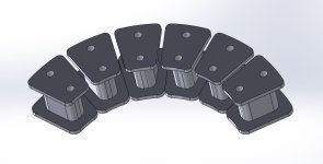
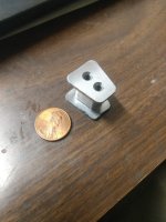
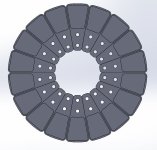
The segments need to be in contact for sure, I don't think overlap is necessary. I had the thought of making the holes
in the center iron ring 'short slots', so that the cores can all be slid inward slightly, to allow them to make hard contact
with each other, before tightening down. The steel ring will further connect the flux path.
(might even be able to get by with just one small center hole)

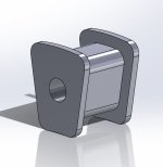
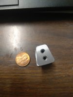
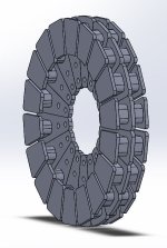
18/16 needs to have a diameter, and a pole length. Things are moving faster than I can draw! But heres a drawing of a
8" diameter stator, with 40mm cores. They turn out to be 40mm H., 20mm W., by 30mm W. top. With 2 -3mm gaps.
Not precise, but not far off either. (8" stator results in a 9 -9 1/2" motor, which is all that will fit in my bike, and a good
size for a hub motor.)

Stator core spacing..jpg

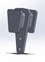
(Looks like your new rendering is this size already)

Dual stator design is actually a single stator, but in two pieces, the cores on each side of the center iron are wired as one
coil. The center iron is just a way to hold the cores well. At least thats the way I see it. Different combinations are possible
with this design.
There will need to be holes in the axle flange for the wires of the coils to go between, for both sides.

It's a dual rotor motor, which is an out runner, and a more bicycle friendly design. It can be a hub motor, or a mid drive.

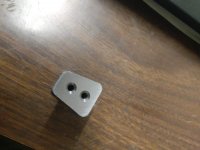
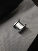
Holding the cores solid, with the least amount of material, easiest construction, and lightest method is the tricky formula.
At the moment, the center ring is looking pretty good, but I'm not completely sure about weight, I have to do some tests.
Probably going to be close enough though.

The new rendering you have is awesome, I like it a lot, and I really wish that it could be done, it would be nice to put an
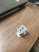
aluminum ring on both sides of that and bolt it down. But I fear that the strength of this powdered iron isn't up for it, and
I'm not sure that even winding wire on them will go very well, or bolting them down. This stuff is really crumbly.
Which is why I'm thinking some kind of resin dip, to re-inforce a bit, and insulate for copper. Not much, but would help.

Just my opinion, correct me if I'm wrong. Keep up the awesome ideas, your really good at it! :)
 
Back
Top