APL said:
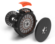
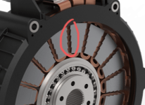
Henery2000, thanks for the info., I wasn't aware of the Linear Labs HET motor per say, but I've seen others like it. Still
don't see how they mount the stator exactly, but it looks like they use brushes in the center.
Your right, they really have it closed up tight, with no cooling that I can see. Big power = big heat.
Mike picked a good topology in the single stator – double rotor design, but very early on in this thread I wanted to ask him one very important question.
Why did he choose an outrunner design over an inrunner design? An inrunner design would bring manufacturing simplicity.
The outrunner design forced him to choose a hard to implement stator design. The difficulty became compounded with the choice of split stator design and opposing coils.
Axial motors tend to generate enough force between the rotor and stator discs to deflect the rotor against the stator and cause a failure. I believe that despite the rotor design where the magnetic forces cancel each other out it was a combination of the stator design and flex and the built up sandwich that led to sufficient lack of rigidity causing the rotor to contact the stator disk at higher rpm.
IMO an inrunner design with the two rotors connected directly to one another via a very rigid shaft inside a motor case will solve that issue. Such a motor can be yoked or yokeless. In either case the stator windings can be placed into direct contact with the outer aluminum casing for better heat transfer.
It is preferable to use a single toroidal wound coil rather than the split design chosen, made so that there are no overhanging loops that don’t contribute to generating flux. in such coils 100% of the windings are active. The HET motor uses such a design as does the YASA and Magnax motors.
I'd consider rotating the coil 90 degrees so to make manufacturing of yoked design with far less material much easier. The HET motor does this and does the Lynch motor.
When Mike posted the pic of the HET motor I was sure that you had stumbled across what I wanted to suggest, but he seems to have missed what some of the best companies have done and why because he was too far down his design path to change.
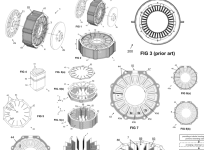
Linear labs does not say how they fix their armature to the motor housing, but they do show a brilliant stator armature arrangement that assembles components around a tape wound split ring yoke and spider. This permits them to use discrete mass produced parts of excellent quality.
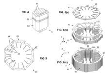
The armature is assembled from power modules that slide over a yoke comprised of a ring that separates into two half moon segments. The power modules are made up of two stators and a coil element.
Mass produced toroidal coils (with very high fill density due to the use of square wire) are wound onto plastic bobbins. The wires from the coils are soldered onto a narrow PCB board, which have long pre-bent coil outlet pins soldered onto them.
The coil output wires are soldered into a separate pcb board that bring all the coils together into the desired connection arrangement...
The coils are wound onto plastic bobbins that are sixed to fit snugged very tightly in between 2 stator poles with a hole in the center, all of which slide onto a split ring to hold everything together. Due to the design of the stator poles which virtually surround the coils they capture all of the magnetic field from the coils.
The coil design is similar to yokeless and segmented armature arrangement that I believe magnax use as well.. at least the mass produced square wire toroid's that insert into the segments.
In most other yasa designs the stators are set into the motor shell so as to cool to the exterior of the shell or have cooling oil injected into the armature portion to perform cooling in larger motors. Some experimental in wheel motor have cooling finds that penetrate the shell and extend into the stator assembly..
I'm not sure what HIT does, what with their hybrid axial and radial flux design, but I suspect its oil cooled.
If you want to attempt a yokeless design here is a paper on the Comparison and Analysis of Stator Plate Holder on Yokeless and
Segmented Armature Machine from the Journal of Physics: Conference Series:
A F Desanti et al 2020 J. Phys.: Conf. Ser. 1577 012039
https://iopscience.iop.org/article/10.1088/1742-6596/1577/1/012039/pdf
and here are the best images I have found on a YASA design
plan view of a motor shell lamination showing the stator holding arrangement.
Before the stators are put in place and potted with epoxy.
and here is the post potting pic
The above images are from the following paper:
Stator heat extraction system for axial flux yokeless and segmented armature machines
H. Vansompel, A. Hemeida, P. Sergeant
Published 2017
Materials Science
2017 IEEE International Electric Machines and Drives Conference (IEMDC)
pay per view paper.
https://www.semanticscholar.org/pap...eida/c35f1a09869dc7f65a6474fb848685dae1c5fa48


