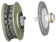
APL's DIY axial-flux motor

That's interesting. I don't immediately see why making it rounded is better. Their comment about lower permeability seems to match with your test results. But you have awesome low iron losses. To make it run faster, you could also reduce the turns.

Are you using delta or wye connection?
 
APL said:
Wow, that all sounds great! I didn't know about the smart phone having a TRRS jack,.. shows how much I know about
those things. It all makes sense now, and sounds like a good, (and cheap), way to go. :thumb:

I'll get the new Ap downloaded, order up a cable or two, and see how all that works out. Thanks for all the great links
and info. The smart phone is definitely more user friendly and portable than the big scopes, plus theres all the other
tools in the PTS box.
Amazon lost the cable I'd ordered, after days of "well, it's still on the way, just wait a bit"...so after they refunded me I ordered again (they can't just resend it? :roll: ). Should be here tomorrow, then I can make a little attenuator and try it out on my android devices with PTS. :) Letcha know how it works out.

(still can't believe nobody just makes an attenuator dongle / BNC-to-TRRS adapter for these phone scopes...there *are* BNC/TRRS cables for other purposes like timecode, video out on some cameras/etc but they don't have the attenuator stuff in them to keep signals from blowing up the phone's input.)
 
I can recommend the Hantek scopes, have one of their base models here (6022) and it's served me really well, iirc I paid about 60 euro for it and it was worth every penny imo.
 
Too bad about the cable amberwolf, good to hear that your still on it though, I'll be interested to see how it works!
On-line disfunction is common these days, but I'm still amazed that they can keep it together as well as they do,..
If you want to see the ball getting dropped just try Walmart! :roll:

Thanks for the Hantek recommendation stan.distortion, I did a little looking around on Youtube and I'm liking it a lot.
It's cool that it uses your PC as the display,.. you get a nice big view. The price is awesome too. :thumb:

I wired it in wye fechter,.. the iron losses are low but I fear that it's because the magnetic circuit is weak, theres just not
very much cogging when I spin it. Who knows,.. we still have to get to the bottom of that. Like you say, we need to find
out how much flux is in the gap, or if the magnets have sufficient T's, or whatever is going on there.
I still have to run the flux experiments for that yet, but I'll definitely get it done. I'm in the middle of inspecting the motor
innards at the moment.
 
I spent the last two days taking the motor apart and measuring everything that I could with the feeler gauges and the
calipers. Seems like the problem is mostly small measurements on several parts, rather than one major one. When the
gap is only .040", 5 to 10 thousands here and there add up.

The good news is that the magnets are fine, and relatively flat, so I don't have to mess with those. It turned out to be
the stator plate being crooked on the axle. Most likely when I added the big washer and tried to clean up that surface.
It's only off by .015", which is actually half of that at .007" and thats at the outer diameter,.. so it's even less at the
washer! Dang,.. just shoot me, these axial's are touchy! Gonna make a radial man out of me yet. :wink:

Stator check..jpg

Well, I'm just going to shim it with a piece of foil,.. screw it, this old axle needs a rebuild anyway, and I'm not in the
mood to go there yet.

There was some odd rubbing on the inner radius of the rotor on the big bearing side, but it might have been from a piece
of wood or tape from assembly. Or it may be from the bearing cap being too thin and weak, which I doubt, but since it's
a possibility I'm going to go ahead and remake it out of some thicker aluminum anyway. Needs to be done.

Thin bearing cap..jpg

So the plan is to make all the tweaks and adjustments, take another millimeter of the spacers and try to get the gaps
down to .8mm, (from 1.5mm), slip some teflon sheet in there and try it again. See if theres any improvement.
The next goal is to get down to .5mm gaps, and maybe try some different voltages and gearing.

But while it's apart I'm going to try to figure out the teslas and permeability of the magnets and cores somehow
so that we have a better understanding of whats up with that. Seems like theres a weak link in the magnetic circuit.
 
APL said:
Too bad about the cable amberwolf, good to hear that your still on it though, I'll be interested to see how it works!

The cable arrived a couple of hours ago, so all I had time to do so far is just plug it inot the headphone jack and put my fingers on the rings (so I'd be an antenna for it) and start up the PTS scope. It does indeed pickup the signal and display it, an itty bitty noisy 60hz hum with other junk overlaid on it, as expected. :)

So once I get some time when I have energy to dig up all the little bits and pieces needed, I'll cobble together one of those attentuation circuits and put a BNC connector on it to be able to use regular scope probe on there, plus a pair of banana jacks to use the various meter leads/clips/etc I have.
 
I started working on a way to mechanically test for the flux in the gap, but it gets very involved, and the results are still
going to be somewhat questionable, so I can't see going through all the effort.

What I really need is a calibrated Gaussmeter, plain and simple. If I'm dealing with building magnetic circuits, then I'm
always going to need to know what the actual Teslas are.

Looking around for a cheaper unit that will fit the bill, the top pick so far is the TD 8620, with probe, good for up to 20K
Gauss, or 2T, and has a 1mm thick sensor that will fit into most gaps. I saw a Youtube that Doctorbass made on it, and the
unit seems to work fairly well,.. so I'm about ready to pop for one unless somebody has any contrary info. ($90.)
Looks like it will do what I need.

https://www.youtube.com/watch?v=kiDKh_-M3bA

Meanwhile, I checked the magnets the old fashion way, using a screwdriver, and noticed that a lot of the magnets are not
up to snuff, I have strong ones, and weak ones, which is not good. Looks like my DYI magnet cutting has turned out badly,
and Larsb was right, I should have just bought some custom ones. :roll: (I still want to try the water jet though)

The T meter will tell exactly whats going on there, but I'm thinking I might have found another good reason for a possible
weak magnetic circuit.

I'm still going to go ahead with the narrower gap, tweaks and tests with the way it is, but I'm starting to formulate a plan
to maybe double down on these rotors, which are too thin, too weak, and two piece.

The idea is to make new rotors with 1/4" one piece steel plate, and use some of the giant 6mm thick wedge magnets that
I found a while back, in a 16P number, instead of the 20P I have now. :?:
https://www.magnet4sale.com/n42-wedge-neodymium-magnet-od8xid4x0-25-22-5-degree/

The big magnets are a little longer than the cores, and will have a 5mm overhang over the end windings, but from what I've
read, some overhang is a good thing... for fringe flux, and hook up.

Thicker back iron, and 1.32T magnets would certainly step up the circuit,.. eliminate any rotor flex, and should get us
closer to seeing if this SMC has a chance. 16P will make it run faster, but it's the SMC's performance that needs to be known.

I drew up the set up in CAD to show what it might look like, a front view to see the size differences, and a side view for
the thicknesses. Let me know if I'm missing something or on the wrong track with this idea.
(Quick drawing's are not perfect, but pretty close,.. I'll do a better one if the idea is viable.)

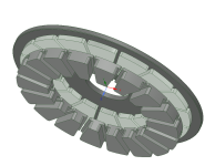
16P V2 rotor..png
Untitled.png
 
Or, perhaps a better idea is to just shelve this motor since it needs so much work,.. a new axle, outer ring and rotors,
and the stator rub problem,.. along with restricted magnetics in the slot, and just start in on V3. I can reuse the cores
at least, and would only need to make some SMC back iron segments.

V2 is fast approaching the point to where any more money that's put into it would be better spent on V3. V3 will have no
magnetic restriction, and a solid rotor that won't flex. If I have to buy magnets, build an axle and outer ring, it would be
better to do it on V3, which I think is a much better design.

V3 Inrunner.png
 
I was trying to think of another test for the core material. One would be to take a core with a bunch of skinny wire turns and feed it a constant current that will come close to saturation, then measure how much pull you get against a piece of thick steel. Repeat with a steel core using same turns count. The steel core doesn't need to be laminated for this test as it's DC. Magnet pull will be a function of the amps x number of turns and you want that to be high enough to approach saturation. Depending on what kind of power supply you have, you may want more or less turns to maximize the amp-turns.

Making laminated axial cores is hard.

Once I saw the core from a large torroidal isolation transformer that was basically a cylindrical donut made of nice laminated steel. Like a big spiral. Something like this could be machined with slots for windings and save some work if you wanted an axial steel core. Machining may be challenging if the laminations aren't glued together well.
 
Your suggested core material test sounds good, might be easier to do if I use smaller pieces of steel, and easier to
power up. :?: I'll see what I can come up with.

I shudder to think about using lamination steel again, but the main problem is just finding it, especially in the shape or
size I need,.. 8" diameter is pretty big. I can purchase large rolls, but not small amounts. It doesn't lend itself to axial's
very well, but if I could find a supply, then I would try to find a way to use it.

I'm working hard at getting this motor back into shape for the next test. I was able to shim the stator plate and get it
centered to within a few thousandth's, so that went well. Next is to make a new bearing cap, and then mill down the
spacers another millimeter, for 1mm gaps

The .030" Teflon sheet came in the mail the other day, and hopefully it will at least keep the stator centered enough to do
a few power test's. We'll see how that fiasco goes.

When the tesla meter gets here I can test the magnets, and that still has to be resolved, but either way I can still run the
motor enough to try different voltages, rpm's, and gearings. The motor does not like the low rpm's, thats for sure.
I'm hoping that 60 or 80v with low gearing will make it come around a little more.
 
I found this older photo of a stator that has the same concept as my motor, but with laminations. The core mounting
method appears to be much weaker than the Ti plate set up I have. I can't imagine that they would have any more luck
than I have with this design, so either this is a failed attempt, or I can only summarize that the air gap balance is the
key to making this thing work without rubbing, and that the stator must be perfectly centered.

IMG_2067 (1) copy.jpg

Unfortunately I don't have the article that it came from anymore.
 
Man, I was hoping the Ti plate would be the ticket. Bummer on the continued struggles! I'm super interested to see the results from the magnetic circuit tests. I still have nearly 2 full bars of the SMC.
 
The Ti plate might be fine, I'm just about ready to give it another go, and concentrating on getting the stator centered
to within a few thousandth's this time,.. now that I have more of the bugs worked out.

Once I get this back together, I'll do some tests on the SMC to try to get to the bottom of that deal,.. I've been waiting
on the SMC verdict too, so that I can stock up on some more bars! What a deal!

Micrometers bars; https://www.ebay.com/itm/Micrometals-Iron-Powder-Block-Core-40-Mix-12-x-3-x-2-5-21-5lbs/282910437725?hash=item41dec6b15d:g:KlwAAOSwlJlaxNxX
 
The new bearing cap is done, the stator is centered, the spacers are shortened 1mm, and the teflon discs are installed.
I have less than .010" room in the gap per side for a feeler gauge, and the magnets aren't perfect, so it rubs slightly
here and there on the teflon, but not enough to make very much difference, and I figure it will wear in.

V2 new cap..jpg

I put the motor back in the bike and ran it at no load for about 30 minutes, and it eventually settled in at 670 rpm @33w
38v. Recharged the batteries and ran it cold the next morning at 40v / 50w / 690 rpm.

So it appears that the smaller gap has slowed it down about 100 rpm, and raised the watt draw another 10 - 20w,
although the slight rub will account for part of that.

Today I took it out for a road test, and the teflon spacers work quite well. I was able to get it up to 535w, which is about
all these little batteries will crank out. I could hear a slight change in sound around 300 - 400w where it was rubbing
before, but the teflon won't allow it do much more than that, and it doesn't slow it down.

So thats the good news, and now I can pump more power into it once I can get a new battery set up going. The motor
feels a little more snappy with the new gaps, and at least it's moving a little farther in the right direction.

My new theory is that the stator will never stay centered as long as the magnets are not all the same strength. Might be
that it's been one of the problems all along. The Gauss meter should get here by this next weekend, so I'll check it all
out then.

Still not exactly a power house of a motor yet, it's drawing about 250 - 300w at 25 mph, and gets a little warm after a
while @ 160 degrees, but it's getting better. :) I'm thinking that some new magnets, and thicker rotors will step it up.

I'll start working on some SMC tests, take some gauss meter readings on the magnets, and start working on some bigger
batteries.
 
What's the current limit on the controller? One thing to try to watch when testing under load is how long it stays at the limit. With my A2B motor, it will only draw about 55A even when the controller limit is set higher than that. It's limited by the winding resistance and battery voltage. With the limit set lower, it will stay at the limit until I reach around 15mph, then it starts to taper off as I go faster.
 
It's been a while since I took a close look at the controller, I was surprised to see that it's not what I thought it was.
Since Crystalyte never did make it easy to tell them apart, I had to do a little research to figure it out. Looks like an
old 12 mosfet 40 amp, 36/48v model. I could have swore that it was the 72v 50A unit.

Well, I'll be buying a bigger controller for the new muscle cruiser project anyway. I bought this one used from HPC, so it
may be that the limit has been altered, otherwise I assume it would be 40A. I see that it has a USB input, but I'm not sure
if it's user, or factory access. Does it work off the USB voltage, or does it need to be powered up?
 
Stepping back just a bit, I want to compliment your CAD skills! You've gone from no modeling at all, to some fairly complex models really quickly!
 
Thanks coleasterling, and thanks for helping me get into it! I mostly use it for the graphic image, and don't pay a lot
of attention to perfect dimensions unless it's going to be exported. But it blows my mind to think that these things I'm
drawing could actually be created by a machine in 3D!
 
I've been looking around at controllers for a while, and I really like the Phaserunner, nice high quality controller from an
outstanding company with great customer support and all the info & user manuals,.. what more could you want.

I especially like the programming and motor scanning mode, which even tells me what the ohm value of the windings are.
Sounds custom made for custom motors, and would work well for these DIY project's.

I'll need to use it on the muscle cruiser project too, which is a little higher output, but still a mid drive, so I can't see it
pulling over 2Kw without braking a cluster or a hub. Not that I'd need it, but with an added heat sink the phaserunner can
output a lot more. Still looking at controllers, but this one's at the top of the list for now, unless someone has any more
suggestion's.

(The gauss meter finally arrived today, so now I can get going with some SMC and magnet testing.)
 
The downside of the ASI controllers is there are so many programmable parameters you can get problems if one is slightly off and nobody actually seems to know what all of them do including the factory. A wrong setting somewhere can make it do some really unsafe things, like runaway full throttle.

If you're getting 40A on your existing controller, that's in the ballpark for bicycle power levels. 100A is a little more fun.
 
Had you considered multiple controllers? At a glance it looks like you get the most bang for your buck, the highest kw/$ from a single controller but it could be worth doing the sums to be sure, there could be a few sweet spots where multiple controllers would make more sense. It would be easy with your coils but would the wires through the centre shaft make it awkward?

A configurable waveform could make sense, you're going to be much nearer square wave than sine with your current pole and magnet shapes but future builds could have very different waveforms. I'm not sure what (if any) controllers offer that option, does Lebowski's? It's the one I'd probably go for from a DIY aspect but I've very little experience of different controllers, some way of driving IGBT modules seem to be the holy grail for big amps at low cost from what I can see (following Axiom closely).
 
Using multiple controllers is an interesting with lots of possibilities, the inrunner design might be a better fit for
something like that, since theres total access to all the coils. Still, this axle does have room for a lot of wires.
The Lebowski controller is another good option, and still on the 'to do' list. I would learn all I need to know from that.
 
I might be having some compatibility issues with the controller and this motor, which is whats prompting me to take a
closer look at ASI/FOC controllers,.. I'm getting an overload audio signal, and auto shut down, at low speeds, from time
to time. And the motor has a shutter or cogging fit at about 300 - 400 watts depending on the speed, as though it's
dropping a phase or cutting out somehow.

Sounds and acts just like chain jump, when the chain runs over the top of the teeth, and is fairly violent. But when I go
direct-drive with the chain to the rear cog, it still does it, so it has to be motor related. Theres nothing on the motor that
can move more than a few thousandth's and mechanically make noise like that, so that seems to point to the controller.

I guess I figure that since I'm running an 18 slot motor on a controller made for 50+, that it's probably having trouble with
frequency issues. I don't think the battery BMS's are at fault, and I checked the phase connections and they're all good.

I'm not sure what the waveform looks like yet, that needs to be determined, but I figure that it's probably a good idea to
have at least one programable controller around for motor building, and I need one with a higher voltage rating anyway,
for the next experiment.

Basically, I figure I've built a high speed motor,.. SMC cores, 18 slot, and I'm trying to run it as a low speed torquer, which
is a noble cause if you can do it, but you know it's probably not right. I'll keep trying, but I think it might do a lot better at
near a 100v and about a 52T cog in back,.. it needs to spin to be efficient and take full advantage of the SMC.
 
I remember some basic controllers that had issues if the e-rpm got too high. We overclocked the processor and got it go run faster. All controllers will have some kind of maximum rpm they can handle. With no load, these controllers would suddenly start drawing excessive current when the e-rpm limit was reached. This limitation should not depend on load as far as I can tell, but there could be something else going on in the software where it makes a difference.
 
The no load rpm is around 700 at the moment, and I have 10 pole pairs, so that's 7000 e-rpm at 40v. If I doubled that
at 80v it would be around 14000 e-rpm, seems fairly low,.. from what I've seen for some controllers specs.

I don't have too many choices for battery voltages at the moment, I can rig a 60v, or 48v packs with more amps, but I can
only double them up without rebuilding them. That would get me 96v and a higher e-rpm, but the motor wouldn't be run
quite that fast under load.

I don't have the gearing for 96v, so I guess I should start with 60v and see what happens. Still need a higher voltage
controller for it though, so I guess I should just get a cheap one for a test and see if it helps things out or not.
I'm making a cassette adaptor for a large 54T chainring in back to try it out.

I'm also making three test core blocks at the moment,.. SMC, solid steel, and laminations. Hopefully we can get some
idea of magnetic percentages from that.

I also did a quick T-meter check on the magnets of one rotor side, and was surprised to see that they're not as bad as I
thought. A lot of 20,000g readings, (1T), but it depends on each segment and theres like 80 of them. I figure I'll have to
print a couple of photos and write in each segment value so I can see how the whole rotor lays out, and if theres any larger
areas that could lead to an unbalance.

If the magnets turn out to be fairly decent, then I get the uneasy feeling that the center stator 'through plate' design is
the problem, and that reducing the flux through the slot was a bad move. But, theres a lot of tests to do first.
 
Back
Top