
Heck, Steve could barely imagine it. It's one of the reasons he retired it and moved on to sailboats (free energy.)fechter said:I remember the behemoth bike. Even with 105 gears, I can't imaging going up any kind of hill with that much weight.
You are using an out of date browser. It may not display this or other websites correctly.
You should upgrade or use an alternative browser.
You should upgrade or use an alternative browser.
Around the world on a solar ebike
- Thread starter solarEbike
- Start date
Just came across this thread. Epic build/adventure!!! Love it!
I've done a semi-similar build with my BikeE electric conversion and found the air deflection of the front mounted solar panel really helps a lot with cruising speed efficiencies. I would recommend you investigate mounting something up front to catch a bit more sun, but if nothing else deflect the air around you for better aero-dynamic effects.
https://endless-sphere.com/forums/viewtopic.php?f=6&t=57751&p=1472101#p1472101
I found on my setup it reduced the average cruising speed watts consumption by over 50W.
Cheers
solarEbike
100 W
Cowardlyduck said:I found on my setup it reduced the average cruising speed watts consumption by over 50W.
Very nice. I like the simplicity of the 3D printed mounts. How have they held up over time? Have you noticed any reduction in solar power from the cells cracking as the panel flexes?
I had a front fairing for while, made from a modified Windwrap fairing. It kept my feet warm and dry during rainy winter commutes here in Northern California and provided enough watt-hours to cover my commute in the summer but I was not able to measure any aero improvements. I tried doing coast-down tests and power to maintain cruising speed. I repeated each test several times with and without the fairing but the variations between test runs were greater than anything I was getting from the fairing.

I even tried fooling around with CFD (Computational Fluid Dynamics) software back when I was dreaming about solar powered velomobiles but got frustrated with the time and effort required to set up appropriate models for this type of analysis. Never got any meaningful predictions about which designs yielded the greatest benefit but it sure made for some pretty pictures.

The main thing I learned is that somewhat counterintuitively, a tail fairing is much more effective on a bicycle than a nose fairing because most of your drag comes from the low pressure area formed behind the bike. Here's my favorite design from the world of HPV racing. Looks like something drawn by Giger.

I found the nuts/bolts have loosened slightly over time, but the shape of the mounts has stayed the same so far.solarEbike said:Very nice. I like the simplicity of the 3D printed mounts. How have they held up over time? Have you noticed any reduction in solar power from the cells cracking as the panel flexes?
I used PLA for everything and for this purpose it seems ok, but if I were doing it again I would use PETG as I found with some other pieces the PLA does not like being under stress or heat for long periods.
Great to see you already tried this also.
solarEbike
100 W
I'm still working on the TailBrain (Arduino-based trailer tilt controller), having fixed coding issues which were causing random reboots and overheating issues resulting from trying to power my Arduino with 13.8V. I think I just lost another photosensor so not quite there yet.
Having figured out most of the details related to setting up bi-directional communication between an Arduino and an iPhone, I decided to procrastinate by taking on a little side project I've been calling the DrainBrain. Using a more modern Arduino based on a 3.3V processor on a board with built-in Bluetooth LE, I tapped into the serial data connection between my CA3 and GPS Analogger and piped the data to my iPhone. The hardware looks like this:

I can view the raw serial data stream on my phone like so:

Or I can parse and reformat the data on the Arduino to create features which aren't available on the CA3. The user interface on the phone can be anything I want as long as what I want is either a screen full of text or a live plot. The idea is that I can avoid writing a single line of code that needs to run on the iPhone by using a general-purpose Bluetooth LE app, written by Adafruit. The app is available for iPhone and Android. One of the trade-offs is that I'm not going to get a cool dashboard interface on my phone but I can live with it. I'm not trying to replace the CA3 screen, only augment it.

So, now I'm rolling down the road entering text commands into a terminal console. I think Steven Roberts is my spirit animal.
My first feature was to calculate the time remaining until the solar chargers enter CV charging mode under current conditions ("CV Min" above). This is useful for planning breaks if I'm concerned about trying to use every bit of available sun. I can keep an eye on the charge status using my phone from up to 15 meters away: handy for taking a noontime siesta under some nice shade while the bike charges.
To calculate this time from the CA3 data took some effort. I needed to figure out the battery's current State of Charge (SoC). Since I'll be resetting the CA3 at the start of each day and the battery will not always be fully charged at that point, I could not use Ah to make the initial SoC determination and had to use voltage instead.
I modeled the LG MG1 18650 cell's discharge and charge curves under different loads and came up with some simple linear formulas to interpolate SoC. This is reasonably accurate as long as the battery is at steady state and over 30% SoC. From that point on, I track the total Wh load and Wh solar charge and use those to update the SoC. The total Wh capacity of the battery is dependent on the rate of discharge and the State of Health (SoH) so I include those in the estimate of Wh remaining in the battery. I also had to switch to an external shunt for battery load measurements since since of my accessory loads do not go through the PhaseRunner motor controller.
Now that I have a reasonably accurate measure of Wh remaining in the battery (within 10 Wh based on 3 road tests so far), I can do all kinds of interesting things with that data. For example, I can estimate the remaining range in miles based on current energy consumption or based on Wh/mile since the start of the current session. I calculate both based on battery alone (in case clouds roll in) and battery plus solar. I can decide on the fly which number best represents the road ahead. This works best when the road ahead has the same elevation changes, headwind and solar irradiance as the road behind.
Alternately, I can enter a desired range and plot the Wh/mile I need to maintain to arrive before the battery's BMS cut-off. These are calculations I've tried doing in my head in the past and they take away from just enjoying the ride.
Ideas for future upgrades include hooking up one the Arduino's analog output pins to the ThIn (throttle input) signal on the CA3 so the Arduino looks like a manual throttle input and using it to create some custom auto-cruise modes.
And finally, a little eye candy. I had some strips of individually-addressable RGB LEDs laying around (Adafruit NeoPixels) and it occurred to me that I could hook these up to the Arduino to communicate battery and solar charging status in a way that's easier to read at a glance and will be easier to explain for roadside show and tell. Red/green is SoC (about 65% in this photo) and yellow is solar charge watts. LED brightness adjusts automatically based on current solar power. Each green dot corresponds to the energy needed for 100 meters of elevation gain so that's handy for budgeting.

Some intermediate steps during the prototyping phase:

I encapsulated the whole thing with clear heat-shrink tubing and silicone. The board status LEDs remain visible, I can still press the reset button and I can take it apart later if I need to change or fix something. The USB cable powers the device and enables updating the code if I want to make changes.

Having figured out most of the details related to setting up bi-directional communication between an Arduino and an iPhone, I decided to procrastinate by taking on a little side project I've been calling the DrainBrain. Using a more modern Arduino based on a 3.3V processor on a board with built-in Bluetooth LE, I tapped into the serial data connection between my CA3 and GPS Analogger and piped the data to my iPhone. The hardware looks like this:
I can view the raw serial data stream on my phone like so:
Or I can parse and reformat the data on the Arduino to create features which aren't available on the CA3. The user interface on the phone can be anything I want as long as what I want is either a screen full of text or a live plot. The idea is that I can avoid writing a single line of code that needs to run on the iPhone by using a general-purpose Bluetooth LE app, written by Adafruit. The app is available for iPhone and Android. One of the trade-offs is that I'm not going to get a cool dashboard interface on my phone but I can live with it. I'm not trying to replace the CA3 screen, only augment it.
So, now I'm rolling down the road entering text commands into a terminal console. I think Steven Roberts is my spirit animal.
My first feature was to calculate the time remaining until the solar chargers enter CV charging mode under current conditions ("CV Min" above). This is useful for planning breaks if I'm concerned about trying to use every bit of available sun. I can keep an eye on the charge status using my phone from up to 15 meters away: handy for taking a noontime siesta under some nice shade while the bike charges.
To calculate this time from the CA3 data took some effort. I needed to figure out the battery's current State of Charge (SoC). Since I'll be resetting the CA3 at the start of each day and the battery will not always be fully charged at that point, I could not use Ah to make the initial SoC determination and had to use voltage instead.
I modeled the LG MG1 18650 cell's discharge and charge curves under different loads and came up with some simple linear formulas to interpolate SoC. This is reasonably accurate as long as the battery is at steady state and over 30% SoC. From that point on, I track the total Wh load and Wh solar charge and use those to update the SoC. The total Wh capacity of the battery is dependent on the rate of discharge and the State of Health (SoH) so I include those in the estimate of Wh remaining in the battery. I also had to switch to an external shunt for battery load measurements since since of my accessory loads do not go through the PhaseRunner motor controller.
Now that I have a reasonably accurate measure of Wh remaining in the battery (within 10 Wh based on 3 road tests so far), I can do all kinds of interesting things with that data. For example, I can estimate the remaining range in miles based on current energy consumption or based on Wh/mile since the start of the current session. I calculate both based on battery alone (in case clouds roll in) and battery plus solar. I can decide on the fly which number best represents the road ahead. This works best when the road ahead has the same elevation changes, headwind and solar irradiance as the road behind.
Alternately, I can enter a desired range and plot the Wh/mile I need to maintain to arrive before the battery's BMS cut-off. These are calculations I've tried doing in my head in the past and they take away from just enjoying the ride.
Ideas for future upgrades include hooking up one the Arduino's analog output pins to the ThIn (throttle input) signal on the CA3 so the Arduino looks like a manual throttle input and using it to create some custom auto-cruise modes.
- Automatically adjust motor power based on distance remaining to destination and Wh remaining in battery.
- Automatically match motor power to solar generation to maintain 0 net watts in/out of battery to prevent overheating the cells in extreme temperatures such as those encountered in desert crossings (40°C / 104°F and up).
And finally, a little eye candy. I had some strips of individually-addressable RGB LEDs laying around (Adafruit NeoPixels) and it occurred to me that I could hook these up to the Arduino to communicate battery and solar charging status in a way that's easier to read at a glance and will be easier to explain for roadside show and tell. Red/green is SoC (about 65% in this photo) and yellow is solar charge watts. LED brightness adjusts automatically based on current solar power. Each green dot corresponds to the energy needed for 100 meters of elevation gain so that's handy for budgeting.
Some intermediate steps during the prototyping phase:
I encapsulated the whole thing with clear heat-shrink tubing and silicone. The board status LEDs remain visible, I can still press the reset button and I can take it apart later if I need to change or fix something. The USB cable powers the device and enables updating the code if I want to make changes.
Dude! Respect for putting the time into developing this!
You should reach out to Justin, I'm sure he would be very interested in this...could even be an optional extra people would buy from Grin with a CAv3.
Might even be incorporated into a future CAv4!
Cheers
You should reach out to Justin, I'm sure he would be very interested in this...could even be an optional extra people would buy from Grin with a CAv3.
Might even be incorporated into a future CAv4!
Cheers
That really looks great. I’ll have to try playing around with an Arduino sometime.
thundercamel
10 kW
Very cool!
solarEbike
100 W
Thanks, guys. I'm pretty happy with the way it came out. If there's sufficient interest, I could spin this off on its own thread. I'm willing to put the source code up on Githhub for anyone who wants to try this although I could probably use some help with modifying it to be more universal. The current version is specific to my setup: CA with solar GPS firmware, distance units assumed to be miles, hard-coded discharge curves and measured state of health specific to my cell type and battery pack, etc.
The range estimation feature should be useful to anyone with a Cycle Analyst, not just the solar minority. My initial results look promising but I'm not confident the accuracy can be easily ported to a general use case. The Cycle Analyst displays state of charge as a battery icon rather than a number and avoids any kind of "miles remaining" estimate. I'm guessing that's because it's hard to do this reliably.
I'm aware that there have been other efforts to port CA data to a smartphone app via Bluetooth. I searched the forum and found a couple of seemingly abandoned threads. Since I can't seem to sort search results by date, it's possible I may have missed some more recent posts. An external Google site search filtered for the last 12 months was not helpful either. My approach is likely unique in that it works with both iOS and Android. And since all the code runs on a physically connected Arduino, it's not affected by temporary loss of the bluetooth connection and subsequent missing data as would happen if you walk away from the bike with your phone while it's charging at a rest stop.
The basic hardware wiring to read the CA serial data is just this. The two resistors are a voltage divider to drop the 5V TTL signal from the CA3 to 3.3V for the Arduino. I only hooked it up to receive as I don't plan to transmit data. The black and red wires are spliced into a TRS cable.

I did a longer test ride last night. I started with a full battery and lots of sun during the first half but almost no sun during the second half so difficult to budget in advance. I kept an eye on the red/green battery LEDs and figured I would turn around early if I hit the 50% mark before my planned turn-around point. I arrived at the midpoint with 70% SoC, charged up to 79% while taking a break and got back home with just 7% left. Perfect.

I kept the phone on the following plotter screen most of the time. It's not much to look at but this was the best feedback on how much energy I was using compared with how much was left to get me to my destination. This plot updates once per second so the sample below is only about 1 minute of travel time.
I can adjust my level of motor assist and get immediate feedback. As long as I keep the red line below the blue line, I will arrive with Wh to spare. Changes in terrain, speed and sun are immediately reflected in the plot. On the outbound half of the trip, I stayed well below the blue line by reducing the level of assist so I would have more assist available on the way back when I would be more tired. Climbing a short hill? No problem, the red line spikes while climbing, plummets when descending and settles back when the road flattens out.

Here's how the LED strips look before mounting. I painted mine black and added a drop of epoxy with microspheres mixed in for light diffusion.

Here's the back side of the encapsulated strip, bonded to a strip of smoke-tinted acrylic plastic. Silicone normally doesn't stick to anything but Loctite 406 with Loctite 770 primer did the trick.

The range estimation feature should be useful to anyone with a Cycle Analyst, not just the solar minority. My initial results look promising but I'm not confident the accuracy can be easily ported to a general use case. The Cycle Analyst displays state of charge as a battery icon rather than a number and avoids any kind of "miles remaining" estimate. I'm guessing that's because it's hard to do this reliably.
I'm aware that there have been other efforts to port CA data to a smartphone app via Bluetooth. I searched the forum and found a couple of seemingly abandoned threads. Since I can't seem to sort search results by date, it's possible I may have missed some more recent posts. An external Google site search filtered for the last 12 months was not helpful either. My approach is likely unique in that it works with both iOS and Android. And since all the code runs on a physically connected Arduino, it's not affected by temporary loss of the bluetooth connection and subsequent missing data as would happen if you walk away from the bike with your phone while it's charging at a rest stop.
The basic hardware wiring to read the CA serial data is just this. The two resistors are a voltage divider to drop the 5V TTL signal from the CA3 to 3.3V for the Arduino. I only hooked it up to receive as I don't plan to transmit data. The black and red wires are spliced into a TRS cable.
I did a longer test ride last night. I started with a full battery and lots of sun during the first half but almost no sun during the second half so difficult to budget in advance. I kept an eye on the red/green battery LEDs and figured I would turn around early if I hit the 50% mark before my planned turn-around point. I arrived at the midpoint with 70% SoC, charged up to 79% while taking a break and got back home with just 7% left. Perfect.
I kept the phone on the following plotter screen most of the time. It's not much to look at but this was the best feedback on how much energy I was using compared with how much was left to get me to my destination. This plot updates once per second so the sample below is only about 1 minute of travel time.
- The blue line is the maximum Wh per mile to get to my destination. It is based on Wh left in the battery and estimated solar Wh to be generated between now and my destination (which, in turn, is based on current speed and current solar watts, averaged over 10 seconds). For example, speeding up means less time in the sun so fewer Wh available for the rest of the trip.
- The red line is my current Wh per mile (also averaged over 10 seconds).
I can adjust my level of motor assist and get immediate feedback. As long as I keep the red line below the blue line, I will arrive with Wh to spare. Changes in terrain, speed and sun are immediately reflected in the plot. On the outbound half of the trip, I stayed well below the blue line by reducing the level of assist so I would have more assist available on the way back when I would be more tired. Climbing a short hill? No problem, the red line spikes while climbing, plummets when descending and settles back when the road flattens out.
Here's how the LED strips look before mounting. I painted mine black and added a drop of epoxy with microspheres mixed in for light diffusion.
Here's the back side of the encapsulated strip, bonded to a strip of smoke-tinted acrylic plastic. Silicone normally doesn't stick to anything but Loctite 406 with Loctite 770 primer did the trick.
thundercamel
10 kW
So do you basically just have to keep one or two LEDs showing green while you're biking, and you'll arrive before running out of charge?
solarEbike
100 W
thundercamel said:So do you basically just have to keep one or two LEDs showing green while you're biking, and you'll arrive before running out of charge?
Sorry, I'm struggling to unpack this sentence...
One or two green LEDs would be 10-20% SoC. On very long days, I don't want to run out of sun and battery 10 miles before my destination as it's a drag pedaling a heavy bike when I'm most tired so I may aim to arrive at 0-5% SoC if the goal was to use as much assist as possible that day. I may try to keep the last 10-20% in reserve for the last few miles, especially if there's a hill at the end.
If I know it's going to rain the next day, I may try to leave as much in the battery as possible.
Also, I currently only have the [strike]88 watt[/strike] 83 watt roof panel plus a small 50 watt test panel on the trailer so I never have enough solar to charge the battery while riding. I prefer to always use some assist. But when the trailer is complete, I'll have a total of 330 watts of solar panels (maybe 250-300 watts actual) so there will be times when I can cruise at a good speed and still (slowly) charge the battery. Range estimation gets interesting at that point because when you're rolling and have a net current flow into the battery, it looks like the bike has infinite range. This happens briefly when I use regen braking.
Not sure if I answered your question?
I should point out that some of this energy budgeting stuff is guesswork on my part. Most of my solar test riding has been only 2 days at a time with one 4 day trip. The habits I will develop when touring for months on end are harder to predict.
ScooterMan101
1 MW
Are you going to buy a couple of commercial flexible solar panels ? ( if so which ones and from where )
or
Are you going to make your own panel ?
If
You make your own panel what cells are you going to use ?
What is the cost of each cell ? Strips and solder , taxes and shipping costs ?
And
On what material will you be gluing the cells to ? ( something that does not contract and expand with the different temps during the day and night )
I would love to see a whole dedicated thread on a solar trailer build .
solarEbike said:Also, I currently only have the 88 watt roof panel plus a small 50 watt test panel on the trailer so I never have enough solar to charge the battery while riding. I prefer to always use some assist. But when the trailer is complete, I'll have a total of 330 watts of solar panels (maybe 250-300 watts actual) so there will be times when I can cruise at a good speed and still (slowly) charge the battery.
thundercamel
10 kW
Oh I see now, there are 10 fixed LEDs that represent the state of charge! That makes sense now naturally.solarEbike said:thundercamel said:So do you basically just have to keep one or two LEDs showing green while you're biking, and you'll arrive before running out of charge?
Sorry, I'm struggling to unpack this sentence...
One or two green LEDs would be 10-20% SoC.
I was thinking that you were doing something more advanced, like red + green LEDs equaled the state of charge, but then green represented how much was estimated to be remaining when you reached your destination at the current level of discharge. More solar and more pedaling would increase the green bars in real time, less solar and more throttle would decrease the green bars in real time.
solarEbike
100 W
thundercamel said:Oh I see now, there are 10 fixed LEDs that represent the state of charge! That makes sense now naturally.
I was thinking that you were doing something more advanced, like red + green LEDs equaled the state of charge, but then green represented how much was estimated to be remaining when you reached your destination at the current level of discharge. More solar and more pedaling would increase the green bars in real time, less solar and more throttle would decrease the green bars in real time.
I understand the confusion now. I posted a couple of different photos showing different ideas I tried out along the way and didn't fully explain. Initially, I used all 16 LEDs to represent battery SoC and later I changed it to just the 10 LEDs on the right. Each LED represents 10% but since I can create any color between red and green, the LED between red and green slow changes from green to red as the battery discharges. I can't quite visually differentiate between 10 different shades but I can read the SoC within 2-3% rather than have the meter jump in 10% increments if the meter LEDs were only red or green.
However, I like your idea of using the LEDs to indicate if I'm currently over or under budget to arrive at a preset destination. Watching it as a plot on the phone screen has been helpful while I tweak the code but including this information in the LED display sounds like a better long-term solution. The current 10 red/green LEDs for battery SoC is taking up most of the available real-estate to communicate a single number. I've been thinking about what other information might be important enough to include in these 16 LEDs and this is a good candidate. Thank you.
The 0-6 yellow LEDs on the left for solar watts have been useful for keeping an eye on trailer tilt angle working correctly and unexpected little things like avoiding stopping in a shaded spot at a red light where it's avoidable. I also made one of the lights blink to remind me to turn off vampire loads when I'm stopped for a while: lights, 13.8V converter, motor controller, etc.
thundercamel
10 kW
You're welcome! If you did implement my idea, the colors could represent the estimated SoC at the destination, and the number of LEDs lit would represent the current SoC. The UPS under my desk flashes the last LED at a different duty cycle to represent the next digit of resolution.
7 lit plus one flashing 500ms on 500ms off would equal 75%. 200ms on and 800ms off would equal 72%
7 lit plus one flashing 500ms on 500ms off would equal 75%. 200ms on and 800ms off would equal 72%
solarEbike
100 W
ScooterMan101 said:Are you going to buy a couple of commercial flexible solar panels ? ( if so which ones and from where )
or
Are you going to make your own panel ?
If
You make your own panel what cells are you going to use ?
What is the cost of each cell ? Strips and solder , taxes and shipping costs ?
And
On what material will you be gluing the cells to ? ( something that does not contract and expand with the different temps during the day and night )
I've purchased 8 or 10 different semi-flexible frameless solar panels over the years for my bike projects. These are easily the best option for 95% of solar bike builders. There are lots of options on the market in the $1-2/watt price range. Stay away from the low end of the price range and try to find a vendor who has been in business for a long time. Ideally, they will take the panel back if it doesn't perform as advertised. Unfortunately, many of these panels do not deliver on their published specifications and, I suspect, most buyers never know the difference because they are not using a watt meter and don't know how to account for cell temperature and irradiance when evaluating the output they're getting.
Based on personal experience, the only manufacturer I can recommend by name is Solbian. I've been to their manufacturing facility in Avigliana, Italy because my sister happens to live an hour away. They do good work but their solar panels were in the $7-8/watt range when I last checked.
The commercially produced semi-flex panels did not exist yet when I build my first solar bike in 2008 so I made my own panels. It was a great educational experience but the end results were more expensive and less robust than the stuff you can buy today. Although, soldering SunPower cells is easier than soldering traditional mono and poly-crystaline silicon cells, the lamination step is no easy matter for a casual hobbyist. I don't recommend this approach for anyone hoping to use their panels in demanding conditions involving lots of vibrations, moisture, dust and thermal cycling.
Here's the one exception: If your name is Bernard Cauquil and you are building your own panel in a facility like this one under expert supervision, by all means please go ahead.
 If you don't speak French the video has English subtitles but you have to turn them on yourself. (Merci Bernard pour cette superbe vidéo!)
[youtube]rOAj7TDuA6M[/youtube]
Given the choice between buying commercial panels and making my own, I went with the "other" option. I contacted some of the people making custom race-grade panels for solar race cars, solar airplanes, etc. and arranged for one of them to make me four custom panels. They use proprietary ultra-light encapsulation to achieve significant weight reductions. If you want SunPower's best cells, prices are in the US$10-20/watt range and lead times can be several months or more. If this fits your budget and schedule, PM me for contact info.
Each of my four panels consists of 4x6 SunPower Gen III bin Le1 cells at 3.62 watts per bare cell. Assuming 5% losses from encapsulation, that's 82.5 watts per panel at 305 grams each. Compared with Solbian's closest equivalent, mine has 6% more power, 72% lower weight and 17% smaller surface area.
I'm mounting these on the bike and trailer by bonding them to a custom-made Nomex honeycomb / Carbon fiber/Kevlar skinned sandwich panels using GE Silicone II as the adhesive per the instructions I received from the pros. The first of my four panels is on my roof. The other three will go on the trailer. I've posted photos here and here.
ScooterMan101
1 MW
Only something like this ...
https://www.renogy.com/renogy-100-watt-12-volt-flexible-monocrystalline-solar-panel/
or this ...
https://www.renogy.com/renogy-160-watt-12-volt-flexible-monocrystalline-solar-panel-back-order/
What do you think of these panels ?
X 2 of them because even 160 x 2 minus real world output , $ 400-% 600 is max for me , I would have to sell many things or take some months to pay off, then need charge controller, etc.
thundercamel
10 kW
I went through this thread again, and I don't think you've discussed your bike frame at all. It started off with a 26" wheel in the back, and then switched to one with 20" wheels front and back. I had assumed you put the motor in the front for the higher efficiency at higher rpm, but what made you keep it in the front now? Possibly keeping a nice gear arrangement in the back?
I've decided that I want my next bike to be like yours except with a mesh seat, but I'm having a hard time finding stores that sell them. Plenty of trikes, some sell overhead steering or a model with a 26" rear wheel, some used ones on craigslist without suspension, but I haven't found a store yet that sells the whole package I want like this.
I've decided that I want my next bike to be like yours except with a mesh seat, but I'm having a hard time finding stores that sell them. Plenty of trikes, some sell overhead steering or a model with a 26" rear wheel, some used ones on craigslist without suspension, but I haven't found a store yet that sells the whole package I want like this.
solarEbike
100 W
thundercamel said:I went through this thread again, and I don't think you've discussed your bike frame at all. It started off with a 26" wheel in the back, and then switched to one with 20" wheels front and back. I had assumed you put the motor in the front for the higher efficiency at higher rpm, but what made you keep it in the front now? Possibly keeping a nice gear arrangement in the back?
I haven't discussed the bike much because the solar conversion and long distance touring could be done with just about any bike. Also, it's just a commercial thing I bought as opposed to something that took some creative problem solving, which is my real interest. However, I do get a lot of general recumbent questions. Sometimes, I'll get a stranger asking me about the recumbent and we'll be talking for 10 minutes before the topic of electric conversion and solar power comes up and then they'll notice that the funny looking roof is in fact a solar panel.
I bought my first recumbent in 2007. It was a "Recumbent USA" trike made in Taiwan. At $1500, it was relatively inexpensive in a world where most recumbents start at $3000 for a base model, mainly due to low production volumes. It came with a mesh "lawn chair" style seat. I hated the seat. The large contact area on my back was always sweaty and the large contact area under my butt gave me "recumbent butt," an uncomfortable numbness due to reduced blood circulation. The hard shell seat was a much better fit for me. Your body shape, health issues, riding style and time in the seat will determine which seat style is best for you. A long test ride is the best way to figure it out.
The motor was a 24V mid-chain drive powered by lead batteries. After 3000 miles, I decided to change to a two wheeler with a higher seat and full suspension. The lack of suspension was brutal on rough roads. The low seat height was a poor choice for my 20 mile a day commute sharing the road with traffic. The three separate tracks (one for each wheel) meant that I couldn't avoid a lot of potholes when riding on narrow shoulders.

In 2008, I replaced the trike with an HP Velotechnik Street Machine. The chain-drive motor died from water intrusion into the integrated controller after 1500 more miles and I replaced it with a BMCv3 geared rear hub motor. Except for a failed clutch, this motor was still working like a champ 16,000 miles later. By then, I had finally gotten fed up with the constant maintenance and alignment issues that come with a traditional rear derailleur. It's especially problematic on a recumbent when your daily route has lots of stop signs. The lower head height makes it harder to see over parked cars so you need to be ready to come to a full stop at many stop signs. Also, because you can't stand up on the pedals, you need to be in a low gear to start from a stop. The motor helps but doesn't eliminate this problem if you've prioritized speed over torque as I had. The frequent down-shifting meant I was wearing out shifter cables every 6 months or so and my derailleur needed constant adjustment.
In 2015, I replaced the rear hub with a Rohloff internally geared hub and got a Bafang BBS02 bottom-bracket drive motor. The Rohloff hub is expensive and a bit heavy but it's the best choice for ultra long distance touring. I never want to go back. Except for a failed pinion gear, the Bafang was still going strong after 15,000 miles when I replaced it with the Grin direct drive front hub for better long-term reliability, regenerative braking and reduced drive train wear over the Bafang. The silent operation was a welcome bonus.

In 2018, I replaced the Street Machine (26" rear wheel) with an HP Velotechnik Grasshopper fx (20" rear wheel) primarily because I wanted both bike wheels and the trailer wheel to use the same tire size. This will come into play on long, remote stretches when I need to carry spare tires. I stayed with the HPV brand because they have a long track record of long distance touring. I bought this as a frame with just the seat, steering and rear suspension and built up the drive train, wheels and front suspension fork upgrade myself.

Also, the Grasshopper folds in half which should come in handy for transporting the whole rig.

thundercamel said:I've decided that I want my next bike to be like yours except with a mesh seat, but I'm having a hard time finding stores that sell them. Plenty of trikes, some sell overhead steering or a model with a 26" rear wheel, some used ones on craigslist without suspension, but I haven't found a store yet that sells the whole package I want like this.
Under-seat steering is common on trikes but much less common on two-wheeled recumbents. I think I stuck with it because I was used to it from the original trike. I like the relaxed hand position at my sides as opposed to the "praying hamster" pose of the above seat steering. For a racing recumbent, above seat makes more sense as it's more aerodynamic. I think the under seat option for touring recumbents is less common because people find it intimidating to learn? After the first few miles, you get used to it.
If this is your first recumbent, try to find a dealer and arrange for some test rides even if that means making an overnight trip. Recumbents come in a much wider array of frame geometries than traditional upright bikes. You won't know what's right for you until you try it.
solarEbike
100 W
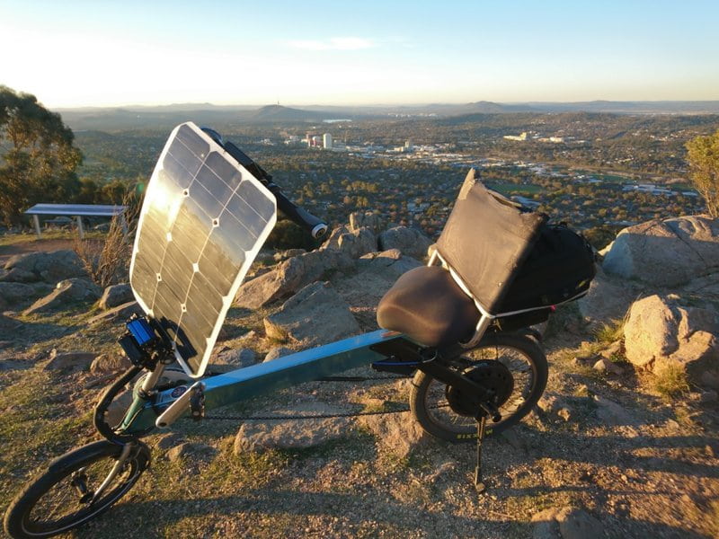
I wasn’t going to post this since it’s only an incremental upgrade to something I’ve posted before but I took some photos and they came out pretty good so I figured what the heck.
I finally got around to upgrading the roof mounting hardware to larger diameter carbon fiber tubes to increase stiffness. The original flexed too much, causing the roof to bounce on rough roads. The new version still flexes a bit but it’s much better. I stayed with the cantilevered design because I really like not having any roof supports in front of my eyes spoiling the view and getting in my way when I get on and off the bike. This was also an opportunity to clean up a dozen details that fell short of my expectations on the original build.

All eight aluminum pieces which fit to the long struts needed to be re-created from scratch to fit the larger diameter. This was done with a band saw and drill press followed by lots of sanding and shaping by hand going from 80 grit to 400 grit, followed by a buffing wheel with aluminum polishing compound. What can I say? Monkey likes shiny.

Indexed tilting mechanism with LED strobe light and GoPro mount. The pivot point is the center of the 8" aluminum (20 cm aluminium) ring which is slightly below my head. Theoretically, I can ride with the panel fully tilted up to 90° left or right but it blocks my view so I'll likely only do that when there's no traffic and not much wind.

I painted the clear vinyl D-channel edge tube to hide the LED wiring.

Improved wire management.

Original carbon fiber tube: 12 mm OD, 8 mm ID. New tube: 19 mm OD, 16 mm ID.

Top panel, including laminated PV panel, honeycomb support panel and LED lights weighs 2.9 lbs (1.3 kg). Everything else, including the carbon struts, all mounting hardware, tilt mechanism, large vertical plate, etc. weighs 3.4 lbs (1.5kg). Solar panel is 24 SunPower Gen III Bin Le1 cells with estimated STC rating of 83 watts with encapsulation losses.

I finally got around to upgrading the roof mounting hardware to larger diameter carbon fiber tubes to increase stiffness. The original flexed too much, causing the roof to bounce on rough roads. The new version still flexes a bit but it’s much better. I stayed with the cantilevered design because I really like not having any roof supports in front of my eyes spoiling the view and getting in my way when I get on and off the bike. This was also an opportunity to clean up a dozen details that fell short of my expectations on the original build.
All eight aluminum pieces which fit to the long struts needed to be re-created from scratch to fit the larger diameter. This was done with a band saw and drill press followed by lots of sanding and shaping by hand going from 80 grit to 400 grit, followed by a buffing wheel with aluminum polishing compound. What can I say? Monkey likes shiny.
Indexed tilting mechanism with LED strobe light and GoPro mount. The pivot point is the center of the 8" aluminum (20 cm aluminium) ring which is slightly below my head. Theoretically, I can ride with the panel fully tilted up to 90° left or right but it blocks my view so I'll likely only do that when there's no traffic and not much wind.
I painted the clear vinyl D-channel edge tube to hide the LED wiring.
Improved wire management.
Original carbon fiber tube: 12 mm OD, 8 mm ID. New tube: 19 mm OD, 16 mm ID.
Top panel, including laminated PV panel, honeycomb support panel and LED lights weighs 2.9 lbs (1.3 kg). Everything else, including the carbon struts, all mounting hardware, tilt mechanism, large vertical plate, etc. weighs 3.4 lbs (1.5kg). Solar panel is 24 SunPower Gen III Bin Le1 cells with estimated STC rating of 83 watts with encapsulation losses.
solarEbike
100 W
billvon said:Are you concerned about the lift/drag you might start to generate if the front of that panel lifts a bit at high speeds?
Hmm... I've been riding around with it for a while now and I haven't noticed anything that negatively affects the bike's handling. You're probably right that there's some lift/drag going on. The original cardboard prototype folded over like a taco in a wind gust.
It might be worth temporarily attaching a reference pole in the front and taking some video to see if it tends to lift and stay lifted. The panel is quite rigid and my top speed it limited to 28 mph (45 kph) by regenerative braking so that helps. I'll eventually encounter winds which make it nearly impossible to ride at which point I can take it off the roof and strap it to the trailer as a last resort.
thundercamel
10 kW
I can't thank you enough for the thorough response man, it's really helpful! I also have had frequent derailleur adjustments required. The hub shifter approach and front wheel motor would actually make me ok with a 26" rear wheel like the streetmachine, and would help my pedals keep up at the higher speeds. I at least have seen that model available on some bike shop websites.
Great work as always on the new roof support and concealed wiring!
Great work as always on the new roof support and concealed wiring!
solarEbike
100 W
I’m taking this new trailer build very slowly since it’s made of expensive materials and is mostly held together by adhesives. This kind of ups the stakes on getting it right on the first try. It would make for a better post if I held off until the trailer is done but in the meantime here are a few out-of-context thumbnails of progress so far: photorealistic renderings out of Fusion 360 and some panel edge protection details.

Mostly, I’m breaking radio silence to share an interesting development that’s come to my attention recently. LightLeaf Solar is a new Canadian startup offering custom-made solar panels uniquely suited for use on an ebike: good weight/power ratio and integrated with a stiff structural panel so they’re self-supporting.
If you who’ve been following my build because you’re considering doing something similar but aren't ready to go off the deep end with carbon fiber and vacuum bagging then this should be of some interest. Had this been available before I started my current build, I would have seriously considered outsourcing the panel building work to them instead of doing it myself.
-5.jpg")
-4.jpg")

PS: If you end up placing an order with them, PM me about how it went so I can help steer others in the right direction in the future.
Mostly, I’m breaking radio silence to share an interesting development that’s come to my attention recently. LightLeaf Solar is a new Canadian startup offering custom-made solar panels uniquely suited for use on an ebike: good weight/power ratio and integrated with a stiff structural panel so they’re self-supporting.
If you who’ve been following my build because you’re considering doing something similar but aren't ready to go off the deep end with carbon fiber and vacuum bagging then this should be of some interest. Had this been available before I started my current build, I would have seriously considered outsourcing the panel building work to them instead of doing it myself.
PS: If you end up placing an order with them, PM me about how it went so I can help steer others in the right direction in the future.
Similar threads
- Replies
- 122
- Views
- 24,020
- Replies
- 22
- Views
- 13,837