fechter said:
I'm not sure on the Puma, but my BMC scooter motor has the windings in parallel (delta).
If I wanted to run a higher voltage, but lower current and keep the output the same, then re-configuring to wye would make sense.
Crystalyte hub motors seem to be in series (wye), so if you rewired one, you could run a lower voltage/higher current. Or you could go really really fast at the same voltage.
For ac synchronous motors and ac induction motors, they could be configurated to run at a high voltage at Y and low voltage at delta.
The ratio between high volt and low volt is 1.73 : 1.
But for BLDC motors with hall sensors, the story will not be the same. The relative phase between the hall signal and the phase back emf will change for the Y and delta config.
Let us use AL1020 hub motor as an example
Phase-sequence = A-B-C
A= yellow winding
B= blue winding
C= green winding
HA = Hall signal of yellow
HB = Hall signal of blue
HC = Hall signal of green.
HA, HB and HC are spaced at 120 elect deg.
Case 1 (Normal config)
The winding is Y connected
Voltage between A and B = Vab
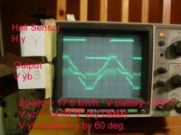
Vab leads HA by 60 deg ( by the controller)
Then voltage in yellow winding leads HA by 30 deg which is the designed phase shift.
Case 2 (Not normal)
The winding is delta connected.
Vab leads HA by 60 deg ( by the controller).
Then voltage in yellow winding also leads HA by 60 deg which is not the designed phase shift.
The phase shift in the case has "advanced" by 30 deg.
I think the motor could still run but it may take an relative higher current at the same load.
Comments:
A) If the orignal design is Y and it is connected as delta, the relative phase between the voltage of winding and Hall signal is advanced by 30 elect deg. The motor could still run at a higher current for the same load. Similar to an poorer power factor in ac syn motor.
B) If the orginal designis delta and it is connected as Y, the relative phase between the voltage of winding and Hall signal is retarded by 30 elect deg. The motor may not run at all.
C) The Hall signals could be inverted and re-aranged to have an 60 deg phase-shift change such that (B) becomes "advanced by 30 deg".