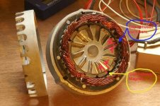
bmc/puma windings

The7 said:
maxwell said:
The Crystalyte 400 series has a remarkably trapezoidal BEMF as it uses windings that span 3 slots (the phases are spaced one slot) with magnets that span three slots (per pole), those slots are also skewed 1 slot pitch making it even better. Next time I get a rig on my bench I will take some voltage and current waveforms.

Thanks for tell us the distribution of the windings of X400 motors.
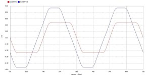
This construction would give an trapezoidal Back emf.

Grateful if you post its back emf waveforms when available.

Any back emf wavform for X-motors.
 
Still in the process of revamping my workshop (new mill arrived last week) so I put the 409 into BLDC (a motor design program) and got these curves.

The smaller one is betwen the centre point and a phase, the larger one betwen phases, memory seems to confirm this is about the right shape for an Xlyte.

I tried a few changes and it made things less trapezoidal, I can conclude that the Xlyte is a well designed motor (as if we didn't know that anyway).
 

Attachments

  • xlytewave.jpg
    xlytewave.jpg
    59.5 KB · Views: 1,788
Noted that the voltage waveforms of the X400 will look like Va and Vab.

Like to see the back emf of these for X400 motor when spinning with hands on an oscilloscope (not only from software simulation).
 
The windings overlap and the stator poles are skewed.

I have one in the garage. When I get time I can stick it in the vise and spin it while connected to the scope. Fortuantely, my scope is within test probe range of my vise.
 
fechter said:
The windings overlap and the stator poles are skewed.

I have one in the garage. When I get time I can stick it in the vise and spin it while connected to the scope. Fortuantely, my scope is within test probe range of my vise.

With skewed poles, the back emf could tend to be approximately sinusoidal.
 
maxwell said:
Skewed poles tend to make the slopes straight, improving the trapezoidlness(?)

Tend to align with your saying. But the flat top will be much round off.
So what will it look like then!?

Still want to see the back emf on an scope.
A picture is worth a thousand words.
 
maxwell said:
An setting skew to 0 in the simulation program gives...
Agreed with your simulation program:

With one slot (60 deg) skewing, the Va (Back emf of phase A) will be trapezoidal with 120 deg flat top.
Vab wil be trapezoidal with 60 deg flat top.

With non-skewing, the Va will be squared.
Vab will be rectangular with 120 deg.

Why do they design trapezoidal emf waveform for the X400 motors
(while others design sinusoidal emf waveform for their BLDC motors)?
 
The Xlytes (and many more good BLDC motors) are designed with a trapezoidal BEMF to generate that 1/6th of a cycle flat top so they are compatible with a rectangular waveform drive. The flat top gives a constant current drive (Drive volts - BEMF) / motor resistance.

Sinusoidal BEMF on the other hand is used (primarily) for motors being driven by sine waves, e.g. off the mains, agian giving a constant current (overall). It is quite a design job to get the BEMF sinusoidal for large motors needing spread windings to do this.

You can drive either sort of motor from the other sort of drive they will work very well with more torque cogging and less efficiency though.

Six rubble bags of crap removed from the workshop so far (2 or 3 to go), it's getting there. Plumped for a new lathe too, now that arrives Friday.
 
maxwell said:
The Xlytes (and many more good BLDC motors) are designed with a trapezoidal BEMF to generate that 1/6th of a cycle flat top so they are compatible with a rectangular waveform drive. The flat top gives a constant current drive (Drive volts - BEMF) / motor resistance.

Sinusoidal BEMF on the other hand is used (primarily) for motors being driven by sine waves, e.g. off the mains, agian giving a constant current (overall). It is quite a design job to get the BEMF sinusoidal for large motors needing spread windings to do this.

You can drive either sort of motor from the other sort of drive they will work very well with more torque cogging and less efficiency though.

Thanks Maxwell.
Your explanation has enlightened me although I am a slow learner.

My enlightened understanding for smooth torque and high efficiency is either :
Case 1 “ to match BEMF with the voltage drive”; or
Case 2 “ to match the voltage drive with the BEMF”.

Most controllers for e-bike are simple 6-step drive type. So a trapezoidal BEMF (like X400 motor) would be a best match.

Most controllers for industrial application are sinusoidal drive type. So an motor with sinusoidal BEMF would be the best match. However sinusoidal dirve controllers are more complicate and may not be justified in e-bike application.

I would expect larger e-vehicles would use sinusoidal drive controllers and sinusoidal BEMF motors because their torque and efficiency are the better than any other waveform drive/BEMF.
 
OK, here is an actual scope trace on a Xlyte 5303. It's surprisingly similar to the simulation, and quite trapezoidal. Measurement is between two phase wires.

Sorry for the crappy quality. I had to use the "garage" camera and it was difficult to maintain a steady speed by hand.
 

Attachments

  • DSCF0007.JPG
    DSCF0007.JPG
    40.4 KB · Views: 3,009
fechter said:
OK, here is an actual scope trace on a Xlyte 5303. It's surprisingly similar to the simulation, and quite trapezoidal. Measurement is between two phase wires.

Sorry for the crappy quality. I had to use the "garage" camera and it was difficult to maintain a steady speed by hand.

Thanks for photo.
You have an very good scope.
 
The7 said:
Thanks for photo.
You have an very good scope.

I got it for free :wink:

It was dropped and was not working, but I was able to locate some cracked traces on the pcb and repair them. I think it is very expensive.

Anyway, interesting how there's a step in the waveform around zero V.

It looks very strange when I turn it very slow as there is some sort of mechanical resonance going on. It also makes a growly sound at this speed.
 
fechter said:
It also makes a growly sound at this speed.

I've wondered what that growly sound at lower RPMs is.... dogs on the trails think my motor is another dog growling at them. From 0-5mph there is a 'tic tic tic' sound. From 5-10mph is the growly sound. Next comes the short 15mph shudder-vibration zone, and then it's smooth as glass and quiet as purring cat after that. Other X5 owners report about the same thing. What do all these noises mean, or what specifically causes these noises?
 
The step is two windings not quite being trapezoidal and not meeting exactly (electricaly not physicaly). If you take a look at my non skewed simulation you will seee where it comes from.
 
fechter said:
Anyway, interesting how there's a step in the waveform around zero V.

This is due to small gap between each section of the winding core and the gap between each magnet. The simulation result may assume these gaps are "zero" width. But this gap is relative large as you can see.

That is why I like to veiw the actual waveform as well as the simulation.
 

Attachments

  • PICT0019comp a.jpg
    PICT0019comp a.jpg
    48.2 KB · Views: 2,982
  • hall_sensors_194 a.jpg
    hall_sensors_194 a.jpg
    45.6 KB · Views: 2,981
fechter said:
It looks very strange when I turn it very slow as there is some sort of mechanical resonance going on. It also makes a growly sound at this speed.

For X400 (X500 as well)
No of winding slots = 3 X no of magntic poles.
All the gaps of poles pass the gaps of the winding slots at the same instance.
This will produce an air pressure change (sound) M times per rotation.
This will also produce an maximum/minimum magnetic attraction/repulsion at the same instance.
M = no of winding slots.
N = rpm of motor.
Assume M=36 and N = 100 rpm
The frequency of this sound is (M*N/60) Hz = (360*10)/60 = 600 Hz
If the casing of the motor is in resonance with this frequency, it will produce a loud sound of 600Hz.

If no of winding slots is NOT equal to 3X no of magnetic poles (e.g. your BMC motor, GL2 motor), all the gaps of the poles do NOT pass the gaps of the winding at the same time.
So the chance of producing loud sound could be much less.
Seems these type of motors will have very sinusoidal back emf and they do not have skew slot at all.
 
Yes, the BMC motor has a nearly sinusoidal bemf. It has 16 magnet poles and 18 stator poles, so the staggering reduces cogging. It does still make quite a bit of noise with a square wave drive.

The noise/vibration I was observing with the Xlyte motor was some kind of mechanical vibration of the parts excited by the cogging. The motor was completely unpowered during this test. I just clamped the axle in my vise and spun the wheel by hand.

The magnetic cogging induces an unsteady force on the motor parts as the motor rotates. The motor parts are all elastic metal and have some deflection. When the frequency gets near resonance, it sets up a 'ringing' in the parts. I'm just not sure which parts are most responsible for the ringing.
 
fechter said:
Yes, the BMC motor has a nearly sinusoidal bemf. It has 16 magnet poles and 18 stator poles, so the staggering reduces cogging. It does still make quite a bit of noise with a square wave drive.

Seems you had said that your BMC is delta-connected ?
Y-connected motors are quieter and have higher efficiency than delta-connected motors because Y-connected motors are not sensitive to the 3rd harmonic in the drive voltage.

Your X-controller is an 6-step drive (not square wave drive).

For an motor with sinusoidal back emf:
Sinsoidal drive = best (minimum noise, smooth torque, higher efficiency)
Pseudo (PWM) sinusoidal drive = good
6-step drive = fair
Square wave drive = poor

IMO. An motor with trapezoidal back emf wil behave similarly using the above drives. (Maxwell may disagree).

Most e-bikes use simple 6-step drive.
Most large e-vechicles use pseudo sinsoidal drive.
Sinusoidal drive could (nearly only) be obtainable directly from the mains at a fixed frequency (60Hz in NA and 50Hz in others); or from motor-generator set.
 
fechter said:
The noise/vibration I was observing with the Xlyte motor was some kind of mechanical vibration of the parts excited by the cogging. The motor was completely unpowered during this test. I just clamped the axle in my vise and spun the wheel by hand.

Case 1
For unpowered motors with trapezoidal BEMF ( X-motors):
If you try to spin it very slowly, the motor tends to align itself to "certain fixed positions" and give the feeling of cogging.
These "certain fixed positions" are positons where all poles are aligned with the winding poles.


Case 2
For unpower motors with sinusoidal BEMF (e.g BMC motor):
If you try to spin it very slowly ( backward if internal free-wheel) , the feeling of cogging is negligible. But the average drag in spinning may be approximately the same as case 1.
IMO. Usually the drag is less.
 
couple of pics of bmc windings
the one with phases drawn on, looks like some poles in parallel,
means that could probably change winding connections for different applications ( not that anyone would want to go to the trouble!!)
puting all in series might be better for higher voltages ( higher resistance),
and puting all in parallel ( on one phase ) better for low voltage.
Certainly works that way for fisher paykel motors, all poles of a phase in series for higher voltage, put all in parallel for low voltage.
Will maybe change rpm of motor too not sure on that.
just tinkering
 

Attachments

  • bmcphasessmall.jpg
    bmcphasessmall.jpg
    180.8 KB · Views: 1,740
  • newoldwindingssmall.jpg
    newoldwindingssmall.jpg
    54.2 KB · Views: 3,012
solarbbq2003 said:
couple of pics of bmc windings
the one with phases drawn on, looks like some poles in parallel,
means that could probably change winding connections for different applications ( not that anyone would want to go to the trouble!!)
puting all in series might be better for higher voltages ( higher resistance),
and puting all in parallel ( on one phase ) better for low voltage.
Certainly works that way for fisher paykel motors, all poles of a phase in series for higher voltage, put all in parallel for low voltage.
Agreed.
Thanks for photos.

Suppose there are two parallel branches in one phase winding.
If they are re-connected in series, then its rated voltage is double and its rated current is half.
There will be no change in speed, torque and efficiency when the new rated voltage and rated current are applied.
If the original is Y-connected, the new series-connection remains Y-connected. The relative phase shift between the Hall sensor signals and winding voltage remains unchanged.

Of course, one could re-config the new series-connction in delta-connection. There will a further change in rated voltage and rated current (a factor of 1/1.73 and 1.73)
But the relative phase shift between the Hall sensor signals and winding voltage will be changed by 30 deg. You will have great trouble to remedy this phase shift.

Comment:
a) Reconnecting in parallel or series only affects its rated voltage and its rated current

b) Re-configing to Y-connection or delta-connection will affect its rated voltage, its rated current and the relative phase shift of the Hall sensor (Ha) and the winding voltage (Vab).
 
Back
Top