For people who ordered the larger BAC2000 units, you'll obviously need to prepare an appropriate cable harness that includes a pinout of either the TTL level or RS485 level communication leads. Here's an example of how we did a simple harness that has a throttle plug, a 6-pin CA plug (V2 and V3 compatible), and the TRS jack for communication with the standard CA programming cable.
View attachment 1
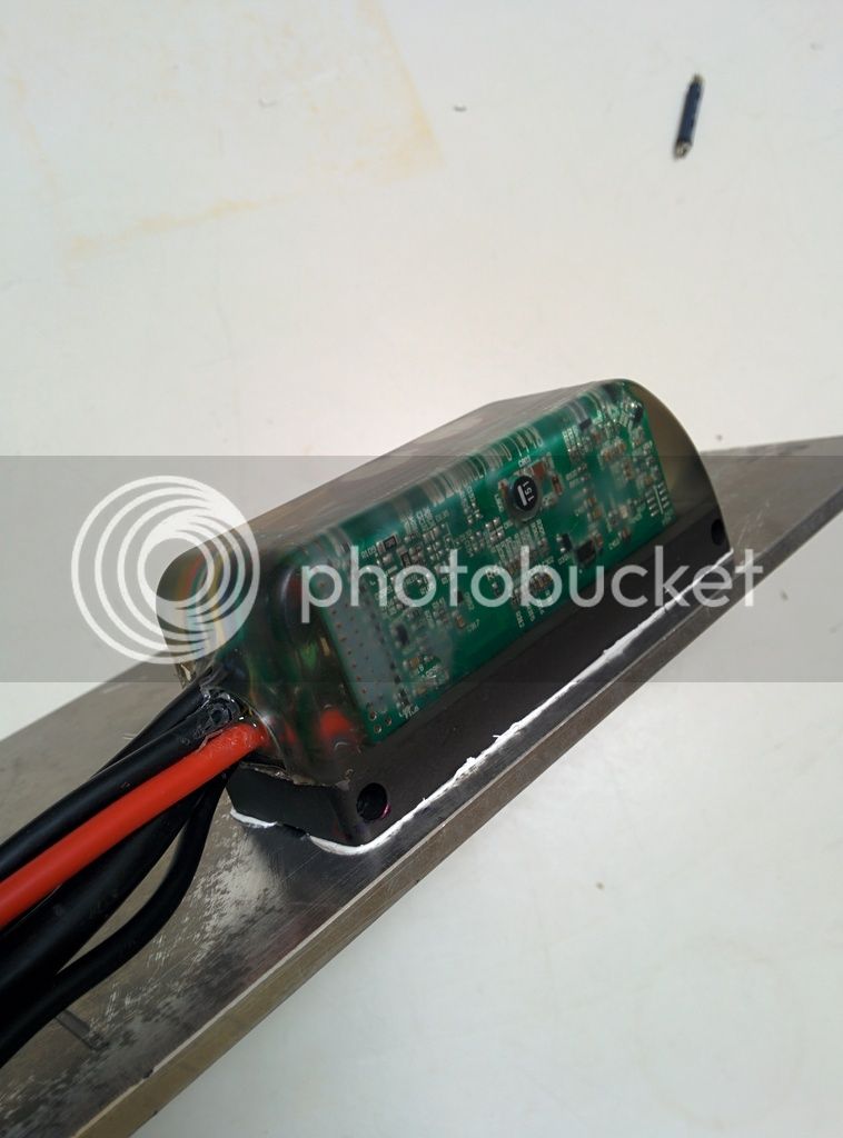
The phase and battery leads hook up with screw down terminals inside the housing cover. On the battery lead, we have a
1mOhm inline shunt resistor crimped to the cable, with the black, blue, and white CA-DP plug wires soldered to it. It's covered in shrinkwrap in the photo unfortunately. And you'll notice that there are some extra thinner gauge red wires on the V+ battery lead. One of these is for the Cycle Analyst V+, and the other is for the key switch input on the signal plug.
You
must connect the
Key-In line to the battery V+ voltage in order for the controller to power up, since that supplies power for all the logic and control circuitry.
View attachment 3
For the 16pin Molex Connector, the pinout from the datasheet is as follows:
View attachment 4
We've found that rather than using the pin7 Throttle Input, it's more convenient to hook up the throttle signal line to pin 6, the analog brake input. In the BACDoor setup utilty, you can then choose your throttle signal source to be the analog brake input line, and then again map this so that you have throttle signal from say 1.2-4.0V, and have regen mapped to start at 0.8V and go maximum at 0.0V, and then you'll have proportional acceleration and braking with a single wire. Of course if you have separate analog throttle and ebrake signals on your vehicle, then each should use the appropriate pin.
View attachment 2
Hope that's enough to get people started.