Definitive Tests on the Heating and Cooling of Hub Motors

fellow said:
Sooner or later we must accept motorcycle cooling soulutions (big radiator, fluid cooling) as the only way of getting into the 10+ kW terrirory.

That would be true if our motors weren't drastically more efficient than ICE's. Zero emotos run at 40kw output and those motors are passively air cooled, and for high demand racing people simply add an inexpensive and lightweight blower to force a high velocity flow over the outer shell. I run my hubmotor at 27kw peak with a simple bladed through motor ventilation approach.

The guys running the oil bath approach have demonstrated that it's superior to the liquid cooling approaches that don't put the coolant in direct contact with the copper and stator steel, because it eliminates the temperature spikes of intermittent use by moving the heat away from the copper more quickly resulting in a more homogeneous temperature throughout the motor. They've come up with some novel ways to all but eliminate oil leakage.

What baffles me though is that the final step in heat transfer is completely ignored due to the simple fact that by leaving the exterior unchanged the only way the motor can dissipate more heat is if the exterior shell of the hubmotor is hotter than without the oil. Anyone who has run a hubmotor in stock form knows the outside shell can get very hot. I asked too much of my first hubmotor and pushed it to near failure, and when I sprayed it with water it sizzled away quickly. Sure the oil bath heats the shell more quickly, so early in a ride it dissipates more heat, but the ultimate bottleneck for heat transfer remains unchanged. The gains from having more heat dissipation early and having a more homogenous motor temperature (which also increases efficiency a bit due to lower copper resistance) may be enough for guys like Emmett who run modest power, but most of them would see bigger gains from proper controller tuning (another all but ignored factor in keeping motors cooler), and many, if not a majority, want to push well beyond 3-4kw with their hubmotors.

Hubmotor covers are mostly smooth, which reflects how clueless the manufacturers are when it comes to heat transfer. That leaves the door wide open for large improvement. I'm not talking necessarily adding lots of large heat sink fins to the covers, though I'd probably go that route if I had aluminum welding capability. Normal operation means we have a natural forced air flow, so cutting small closely spaced channels should be able net double the surface area without impacting the structural integrity of the covers as long as you don't get carried away too much near the center. For good measure I'd add a handful of blades at the perimeter to induce much more air flow from the center like I saw with a smoke test of my ventilated air cooling approach that includes exterior blades.

Note that if you increase the surface area of the interior of the covers in a similar manner, it will net significant gains in heat transfer for a motor without oil fill, especially if you include interior blades that increase the turbulence and flow velocity of the air at the stator and end windings. It wouldn't net the homogenous motor temperature benefits like oil fill does, so there would still be temperature spikes in the copper, but stock hubbies dissipate heat amazingly well considering the layer of air between the stator and shell, and this change would significantly improve upon that. I'm working with a motor manufacturer to incorporate these ideas in the motor shell and covers, and we're expecting to be able to increase motor power by 30-40% on the scooters they produce.

John
 
John in CR said:
... What baffles me though is that the final step in heat transfer is completely ignored due to the simple fact that by leaving the exterior unchanged the only way the motor can dissipate more heat is if the exterior shell of the hubmotor is hotter than without the oil. ...
that's easy to answer: if you can run your bike WOT until the battery is empty than your have enough thermal mass and surface. no need to add fins and make the surface bigger. problem will be, that as soon as you realize that your motor that was running fine at 2kw now runs fine with oil cooling and 4kw, you will make it run 6kw and your problem starts again. that is where fins will help.
 
izeman said:
Punx0r said:
I wonder if you've increased the average exterior temperature of your motor but not the peak. That would go some way to explaining where the extra thermal energy might be going....
the temperature that the motor can get rid off is the same as before. what has dramatically changed is the way the heat takes. before there was air between the stator and the magnets/covers, now there is oil which takes the heat from the windings and transfers it very quickly to the case. and the case is in fresh cooler air - contrary to the windings. that way the case heats up earlier and faster. and the hotter it gets the more heat it can shed (delta temp is higher). but the maximum heat it can get rid of is the very same as before.
without oil the windings just overheated before they could transmit all their heat to the case. with oil the windings stay cooler all the time. and peak temp is reduced dramatically.
that's it.

Exactly, and it puts us at the mercy of the thermal limits of the magnets, which is lower than the coating on the copper, and it adds a more direct thermal connection of the primary heat source to the magnets. There is some overall efficiency gain from keeping the copper temps lower, but for most there's a lot more efficiency gain from proper controller tuning which also greatly reduces the potential for burning up the windings.

Something I haven't seen mentioned is that using an oil bath probably makes a thermal sensor mandatory. The stock motor on my cargo bike, which still has no thermometer has been tortured on uphill grades for 6 years, and the only reason I didn't burn up the windings long ago is because I can easily tell by throttle response under load when the motor is getting too hot. Unless the magnets getting hot is what has given me that "feel", then I won't be able to sense the motor's limits using an oil bath, because the copper temps won't spike.
 
izeman said:
John in CR said:
... What baffles me though is that the final step in heat transfer is completely ignored due to the simple fact that by leaving the exterior unchanged the only way the motor can dissipate more heat is if the exterior shell of the hubmotor is hotter than without the oil. ...
that's easy to answer: if you can run your bike WOT until the battery is empty than your have enough thermal mass and surface. no need to add fins and make the surface bigger. problem will be, that as soon as you realize that your motor that was running fine at 2kw now runs fine with oil cooling and 4kw, you will make it run 6kw and your problem starts again. that is where fins will help.

I run miles of uphill grades at traffic speeds, so assuming a sealed motor an oil bath with no change in the surface area will increase power limits only a negligible amount.
 
My experience is a motor exposed to a good air flow can dissipate a tremendous amount of heat. When you stop, there's no more air flow and the temperature of the housing will increase rapidly. With good air flow, the housing could be barely warm while the windings could be burning up. The limiting factor seems to be the rate of heat transfer from the copper to the outside.

There are ways to do thermodynamic calculations knowing the thermal conductivity and length of all the path sections, temperature differential, surface area, air flow, etc.

Blowing air through the windings with a blower works great. I could more than double the continuous power rating on my BMC motor with enough air. This eliminates a bunch of path resistance and the heat exits the motor in the hot air. Downside is dust/water ingress.

If a sealed system is desired, lowering the thermal resistance between the copper and outside is the primary obstacle. Once the heat is on an external surface, getting enough surface area and air flow is fairly simple. If you travel mostly at speeds over 15mph or so, pretty much any hub motor will have enough surface area. If you travel mostly at low speeds, then a fan might be needed. Cooling fins on the surface of the motor would help also.
 
You could easily double the surface area of a motor cover by turning a series of concentric rings, as long as they are as deep as they are wide (think small).
 
fechter said:
There are ways to do thermodynamic calculations knowing the thermal conductivity and length of all the path sections, temperature differential, surface area, air flow, etc.

For a stock DD hubbie the stator to shell heat transfer is definitely convective above low rpms, and my estimates of the convective heat transfer coefficient from stator to shell and shell to the environment ended up very close to the results proven by Justin's detailed testing, so I didn't bother taking calculations further. I did some rough calculations using conduction, and I quickly realized that wasn't how our hubmotors move heat except while stopped. It was scary enough that I'll never simply stop if a stock motor gets hot out of fear that I'll roast the magnets. That's also a big part of why stop-n-go in heavy traffic can be so dangerous for a motor, because with every start beginning at 0% efficiency heat builds up quickly in a motor already at operating temperature.

With geared hubbies like your BMC the heat pathway is worse than with DD's. Plus the much smaller surface areas makes matters worse in terms of heat transfer, so your observations aren't surprising. That's why MWKeefer was enjoying great success with oil fill on geared hubbies for years before others started following suit. It's just not the panacea that some try to make it out to be with larger DD hubbies, especially as we start leaning on the power, just like simply drilling holes in side covers moves a quite limited additional amount of heat while running.

Regarding ingress of water, grit and debris, I'm not aware of a single failure other than Zappy killing some ventilation fans crossing a stream. He rides his DH bike with the big diameter vented MagPie in a small wheel in all kinds of off road conditions. So my initial worries about stuff getting in the motor when I cut open my first motor were overblown. Now I don't worry at all, though I only use bikes with sealed hubbies for riding on the beach. I just keep all holes or slots small, and make sure the exhaust vents are at the extreme perimeter, so if something gets in it can get back out. I did hear a tiny rock rattling around in my motor once, but it came right back out before I had a chance to stop and investigate. I'm actually surprised by the lack of problems for the guys with the giant holes in a pizza pan ventilation approach, because something of troublesome size can get in and be trapped.
 
Punx0r said:
You could easily double the surface area of a motor cover by turning a series of concentric rings, as long as they are as deep as they are wide (think small).

Yes, but that would definitely weaken the covers. With a lot of motors I'd expect the cover to snap along one of those circles just while putting lateral pressure while opening or closing the motor. You'd need to cut just arcs and leave something like spokes uncut unless you went back and welded on some aluminum angle iron, which could also double as blades.

Keep the idea juices flowing for a solution that doesn't require a CNC. A Dremel would take too long. I've been thinking of something along the line a a rig using a small angle grinder and a metal cutting blade instead of a consumable disc that changes diameter. Make the jig so it can't cut all the way through, and do the channels radially. Maybe make some radial evenly spaced around and then go back and make parallel cuts to fill in the pie shapes.
 
One of the problems I have with blades or other additions to the exterior of the side covers is the interference it can have with drive train and brakes.
On one side I've got a 7 speed freewheel, and on the other side my disc brake and caliper.
When in first gear the chain runs extremely close to the side cover. Any blades would just hit the chain unless they were less than 2-3mm tall. Even then if my chain fell off into the gap between first gear and the side cover, all hell would break loose with anything attached to the side cover on that side.

For the disc brake side, the caliper is mounted only a few mm away from the side cover, so no blades could be mounted anywhere near the perimeter where they would be most effective. Pretty much the only position I could mount exterior blades is under the inner section of my disc brake. I may try this, but not sure if will do much.

So the caveat needs to be added, any exterior fan blades on an E-bike hub motor will only be easily possible if you only have a single speed freewheel (or none) and no disc brake.

Cheers
 
Cowardlyduck said:
One of the problems I have with blades or other additions to the exterior of the side covers is the interference it can have with drive train and brakes.
On one side I've got a 7 speed freewheel, and on the other side my disc brake and caliper.
When in first gear the chain runs extremely close to the side cover. Any blades would just hit the chain unless they were less than 2-3mm tall. Even then if my chain fell off into the gap between first gear and the side cover, all hell would break loose with anything attached to the side cover on that side.

For the disc brake side, the caliper is mounted only a few mm away from the side cover, so no blades could be mounted anywhere near the perimeter where they would be most effective. Pretty much the only position I could mount exterior blades is under the inner section of my disc brake. I may try this, but not sure if will do much.

So the caveat needs to be added, any exterior fan blades on an E-bike hub motor will only be easily possible if you only have a single speed freewheel (or none) and no disc brake.

Cheers

You're right. I didn't consider that while trying to fixed the covers weakened by concentric circles. Blades belong at the perimeter anyway where they are most effective, and then radial blades can be out of the way. Using sizable blades like I have on my motor, are only needed on one side and they will draw air from both sides of the motor. I was quite surprised when running a test with dense smoke by how strong the left to right side air flow was outside of the motor, especially since my bolt on rims mostly block the pathway. The right side blades create a strong flow through the motor, and probably even greater flow across outside the motor. If I had heat issue at all, then blocking the holes in the rim to prevent cross flow, would be the first thing I would try in an attempt to increase flow thru the motor.

Another thing to direct more air at the covers to increase the coefficient of convective heat transfer is using air deflectors and/or scoops. The sides of my swingarm battery box were too plain looking, so I came up with air scoops to dress them up, and at that size they grab significant air and send it at the motor. Here's a pic. You can also see my radial blades and the limited area for crossflow from the other side of the motor.
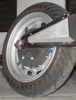
HubMonster blades.JPG
 
You could cut the arcs without a CNC. You don't even have to take it off teh bike. Just mount a lathe cutting tool on the frame, clamped on in a way that allows you to push it further and further into the cover metal to do the engraving.

Rotate the wheel thru the arc you want, and it cuts a thin arc. push it a little harder in, then rotate back to the beginning of the arc. Repeat until it's at the depth you want.

Readjust the tool position down the tube a hair, and repeat the process to make the arcs as wide as you want.


You could do complete circles even easier becasue you could use the motor itself to do the circular motion, while you simply adjsted the tool position. ;)
 
amberwolf said:
You could cut the arcs without a CNC. You don't even have to take it off teh bike. Just mount a lathe cutting tool on the frame, clamped on in a way that allows you to push it further and further into the cover metal to do the engraving.

Rotate the wheel thru the arc you want, and it cuts a thin arc. push it a little harder in, then rotate back to the beginning of the arc. Repeat until it's at the depth you want.

Readjust the tool position down the tube a hair, and repeat the process to make the arcs as wide as you want.


You could do complete circles even easier becasue you could use the motor itself to do the circular motion, while you simply adjsted the tool position. ;)

That might just work since those cast AL covers are so soft. Have you ever done something like that? If so, do you think we could get nice clean square cut channels?
 
I haven't done it using a bike frame to hold the tool, but I had to make a little notch in something with my lathe and rotated the piece by hand like that instead of using the motor. It wasn't fun and took a lot longer than I liked, but it worked ok.

The hardest part is gonna be clamping the tool in the correct orientation, and might be easiest to actually use a lathe tool holder set, bolted to something designed to clamp to the tube size you've got on a particular bike. But there are a lot of ways to make a clamp out of all sorts of repurposed materials, many of which ought to be easy enough to also secure a lathe tool to, and some of which would allow separate adjustment of the tool angles vs the clamp-to-tube angles (which is probably easier to use to do this with).


As for a nice square cut, you would actually want a rounded channel, like a U, with the rounded part at the bottom of teh channel. This leaves less chance of a stress riser problem, cuz the forces of any bending/flexing don't get concetrated along the sharp lines a square channel would have.

Plus, I expect turbulence in the air would prevent much of it from flowing down into the small squared edges of a channel, making that part of the surface probably less effective anyway, so the U would likely be just as good or even better at heat transfer. That part is a guess, but I am pretty certain about the stress issue.
 
I have a pair of MidMonsters with the built on alloy rim still on that I've been planning to turn into a Hanebrink-like 2wd. That would be a perfect comparison test. They have really thick AL shells so I can easily add a lot of surface area, though inside will be tougher, but I can directly compare stock to added surface area dry by setting the controllers identically and head up the mountain. I'll get some of the high temp epoxy from the factory that the slather on the end wind extra copper, and use that to essentially pot the hall board and hall wires, along with anything else that may be sensitive to ATF, and do my first oil bath. Direct comparisons like that will settle a lot of these issues, and as long as the bike is as fun to ride as I think it will be, despite the small tires, then I'd be willing to follow it all the way thru. That would include buying another motor if necessary to directly compare what I consider well ventilated to oil with no shell changes, as well as to with the shell changes I believe are necessary. These only have one side cover, but I can go overboard on the cover, and just do channels for more surface area on the fixed side.

If I can demonstrate a useful benefit with dry but added surface area, then I'm sure the factory will fund me in the form of a free motor or two and the epoxy I need for experiments with oil. First, I have to get the 2wd going with stock motors, or a delta leaner similar to Willow's, so I can make sure they'll run the same temps in stock form, or adjust airflow so they do.

While the motors are quite different from common hubbies making rpm and power input numbers invalid to apply to other number, as long as I make sure there's no test bias (that's why I'm thinking now a delta leaner instead for equal external airflow), then I just have to follow it all the way thru and include plenty of riding styles and speeds in the tests, to settle a lot of disagreements once and for all. Maybe I can even figure out a way to virtually eliminate oil leaks. These have through axle wire harnesses and rubber axle seals, so a weep tube to let the motor breath with temp changes with a bit of cotton or similar on the end to catch oil drips, like one of the guys used with success in the original thread, seems like the way to go. If oil adds to much drag at 2krpm though, the testing would get cut short, because these motors are ultimately destined for mid-drive use at high voltage where I already know ventilated works extremely well. If I can stay totally sealed, that would be more desirable, so I'm actually rooting for oil cooling with added surface area to prove 20kw capable.
 
Seanpaul123 said:
The thing i know is that a "hub motor" is one that is "inside-out" the windings are inside (in the RC world they call them out-runners rather than in-runners).
The Vectrix has a conventional motor mounted in the swingarm and directly connected to the rear hub (which contains a single ratio planetary gearbox with a reduction ratio).
The issue with a hub motor is that the windings are inside and they're the part that generate the most heat. It's fundamentally much harder to cool this "inside-out" setup.
On the Vectrix the windings are on the outside (not exposed, but on the outside in relation to the magnets). This makes it much easier to get airflow and thus cooling.
Thus cooling a Vectrix motor is easier than cooling an XM motor. (Also the mighty V has mechanical gearing on it's side whereas an inside-out hub motor has no gearing other than changing the rolling circumference)
Putting fins on the outside of a hub-motor may help a little but not as much as on a standard motor.
Another approach to reliability is rather than cool it more make it more robust to higher temperature usage. Cooling is the better approach but you might find it difficult.

I agree to some extent, especially that outrunners can be harder to cool. I've solved that on mine by well ventilating it, but that's no solution for something sold to the public. eg I avoid riding in the rain for lot's of reasons, and one of them is to avoid sucking water into the motor. Screened intake and eliminating hall sensors in the motor could change that.

Regarding added external surface area, I disagree. The oil bath some guys are using gets the heat to the shell without issue, so adding surface area will result in a direct increase in heat rejection. With a dry motor it's less direct, because it also requires better heat transfer to the inside surface of the shell. Manufacturers though have ignored the inside as much as the outside with smooth flat surfaces on both, so there's opportunity not only to increase the surface area, but also greatly increase the coefficient of thermal convection by increasing turbulence and flow velocity where it's needed most. I've done that with success on my ventilated motors as well.

Another part ignored by manufactures is getting more outside air flow to the motors. Blades at the perimeter of the spinning motor help tremendously in this regard as does simple air ducting.

The Chinese are so stuck on what they learned with 10's of millions of low powered ebikes that they don't seem to even know how to set up a controller for today's high powered hubbies, and heat transfer has been totally ignored despite it being their number 1 limiting factor. I recently had a controller tech refuse to set up a controller with less than a 2:1 phase/battery current limit ratio, because it wouldn't have any takeoff torque. I'm sorry son, but I've run that ratio as low as 1.25:1 on a bike that would bite you bad if you weren't extremely precise in twisting that throttle and going anywhere close to WOT on launch would put you on your ass. That's all fine though because it gives us an open field for improvements as tinkerers. I was just lucky to hook up with a factory that had to address the areas you mentioned, so the resulting motors are the highest efficiency with the highest rated parts inside. eg I was trying to get the magnets out of one and didn't care if they were ruined, and even after sitting directly on an electric stovetop burner for 30min most of the epoxy hadn't released and I had to chisel out most of the magnets that were still surprisingly strong after extreme heating. Despite having the best hubmotors they can't differentiate themselves based on that, because buyers only care about the power rating, which means great prices for me.

You mentioned the "mighty V" regarding Vetrix. I've never ridden one. What are bumpy roads like with that tremendous unsprung weight. I'm trying to figure out how much I can reasonably improve mine, so feedback might help me avoid a wild goose chase having to learn about suspension, which I know nothing about at this point.

John
 
Sounds like an interesting test in the making, John.

Regarding the grooving and weakening of the cover, it's a tradeoff. Rounded bottom to the groove(s) is definitely a good idea. I was thinking a groove size on the order of 0.5mm, maybe even less. Think of it as more of a pattern or a very poor finish on a lathe. I'd hope that the agitation of the air caused by the spinning motor would prevent stagnation in such small grooves, which would otherwise reduce their effectiveness. Small features (and maintaining part strength) are the key to maximising surface area, but we need to ensure adequate air flow.

In fact, screw it. Cross-cut the covers and create a pin-fin effect :D
 
John in CR said:
You mentioned the "mighty V" regarding Vetrix.

John

Well, the guy you quoted was just a copy/paste spammer, who copied most of that post from this 2009 post on Visforvoltage:
http://visforvoltage.org/forum/6315-cooling-hub-motors#comment-36605

(and replied with generic stuff to some other threads) just to put their spam signature in via their profile. (they also listed their location as USA but they were posting from Pakistan, and they came up as a spammer in other databases, too. The same person or group has signed up to spam for the same websites a few times recently).


So you might have to talk to Oatnet here on ES about the Vectrix stuff. (there's others with them too, but I don't remember who).
 
Punx0r said:
Sounds like an interesting test in the making, John.

Regarding the grooving and weakening of the cover, it's a tradeoff. Rounded bottom to the groove(s) is definitely a good idea. I was thinking a groove size on the order of 0.5mm, maybe even less. Think of it as more of a pattern or a very poor finish on a lathe. I'd hope that the agitation of the air caused by the spinning motor would prevent stagnation in such small grooves, which would otherwise reduce their effectiveness. Small features (and maintaining part strength) are the key to maximising surface area, but we need to ensure adequate air flow.

In fact, screw it. Cross-cut the covers and create a pin-fin effect :D

With straight radial cuts it wouldn't weaken the shell. I don't know about air flow through .5mm cuts, and I'd think they'd get clogged with road grime...at least for me since I never wash my bikes other than a quick rinse after beach riding. I found salty beach sand years later in lots of places on my cargo ebike that Luke got hit with the rogue wave. Using aluminum bolts for pin fins is interesting, and I like it because it allows inside and out fins, and I can adjust them to close proximate to interior stuff (screw in till it touches and back off one turn). Time consuming, but not too bad for someone without the right metal working tools.

I don't have side clearance issues, so quick calculations tell me pin fins using aluminum bolts is the way to go. Using just 50-60 8mm bolts sticking out 10mm doubles the surface area of my side. That's not counting the heads if left on, or slicing them in the center to further increase surface area. The threads themselves add over 50% to the surface area over a straight pin. If I go to 12mm threaded rod and let it protrude 15mm, then 60 in each side doubles the surface area of the entire shell, and it guarantees an improved coefficient of convective heat transfer. If I drill the holes in radial arcs, it won't look terrible either. I just medium lock tight them in for the dry testing, and then back them out to near flush inside and epoxy them in place to prevent oil leaks for the oil bath. The boys can even help me by tapping the threads. It even gives me a way to do aluminum heat sinks on HubMonster's steel bell housing if this works out well. Best of all just simple tools and no welding required.

I like it. Thanks for stimulating the idea by mentioning pin fins Punx0r.
 
amberwolf said:
John in CR said:
You mentioned the "mighty V" regarding Vetrix.

John

Well, the guy you quoted was just a copy/paste spammer, who copied most of that post from this 2009 post on Visforvoltage:
http://visforvoltage.org/forum/6315-cooling-hub-motors#comment-36605

(and replied with generic stuff to some other threads) just to put their spam signature in via their profile. (they also listed their location as USA but they were posting from Pakistan, and they came up as a spammer in other databases, too. The same person or group has signed up to spam for the same websites a few times recently).

Wow, f'ing spammers are going to a lot of trouble to make an account look real. A quite topic specific cut-n-paste from somewhere else...wow!
 
They do it all the time; most of the time we nuke them before they get quoted or replied to. ;)

(and theyve been doing it for this whole millenium so far, andprobably before
that, on forums, comment-enabled sites, and mailing lists, among others. )

Though usually it's not topic-specific, or tehy'll pick a verylong topic and copy/pasta from the beginning of it instead of some other site. Also, thye usued to just copy/paste the whole thing--this one was actualy edited at it's beginning, probably to fool the usual spamchecks people (or scripts) do: highlight the first sentence of suspected spam, and do a websearch on it, see if it turns up anywhere else.
 
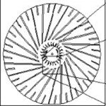
Those look interesting richdeloup. Are they all raised ridges or blades, or are some of them slots? How tall are they? Does the inside face have raised relief too?
 
I really don't know John, I poached the drawings from the net and was wondering how it could be improvised?

I've had a blank disc made up to check for fit and how deep is possible for the ridges, however have also thought that there could be some airflow on the underside and some contact areas?
It doesn't have to be too strong, so am asking the CNC guys how much they can cut out without failure....
I'm not sure if the original center bit is meant to be a spinning fan?
I would guess that if it was slightly raised above the slots it could work with the spinning wheel?
 
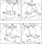
If anyone who knows about this thinks that it may be useful, the guys written a whole paper on it.
I don't mind paying the small fee to get hold of it and passing it on to anyone interested to work on?

Here's the link
http://heattransfer.asmedigitalcollection.asme.org/article.aspx?articleid=1449413
 
Back
Top