Definitive Tests on the Heating and Cooling of Hub Motors

justin_le said:
So what I want to do instead is generate a good ballpark set of thermal parameters for a hub based only on easily measured values. Ideally you could feed in the mass of the motor core, the mass of the hub shell, the diameter and width of the casing, and out comes a decent first order guess for the heat conduction coefficients from the core to the shell, and the shell to ambient, as well as the heat capacities both of the Stator core and the shell.

Our first step in this was the heat capacity values. In the experiments with the 9C motor, I never actually measured or even computed the expected heat capacities of the core and the shell. Rather I played around with the two heat capacity terms in in the model until it fit to the data. The steady state temperature is independent of the heat capacity, so we used that to get the thermal conduction terms, and then adjusted the core and shell heat capacities until the temperature slope rises matched.

I've been really curious to know how well this "model derived" heat capacity compares with a measured value, but it turned out to be trickier than expected to make a DIY calorimeter that was nicely repeatable. Our initial thinking was that we'd put the motor parts in boiling water to get them at exactly 100oC, and then dunk them in a styrofoam cooler with a known mass of room temperature water in it, shake things around, and then from the initial and final temperatures of the water bath we'd know the total heat transferred over.

However, we were only getting at best 5-10% reproduceability when testing the same motor. In part this was because as the motor was lifted out of the boiling water,it was still dripping wet with water, and in the process of shaking it off we'd also be encouraging the evaporation of the water from the surface which would quickly cool the core, so we never knew the exact average core temperature when it was dunked into the water bath. We also found that much to our surprise that all the styrofoam coolers that we had actually leaked between the foam beads. So after a few tests there was a puddle of water building under the cooler and we didn't know at any time how many water was trapped between the beads of foam and not contributing to the heat capacity tests.

So in the end, we lined the cooler with a plastic bag to deal with leakage, and then glued a thermistor to each of the motor cores and side plates. Rather than relying on boiling water to heat the cores up, we could then use a convection oven, and not have to worry about evaporative cooling during the transfer from the oven to the bath.
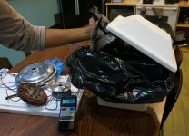
Calorimeter Setup.jpg

Our goal here was to measure the specific heat capacities of a number of existing motor cores and motor shells, in order to see how much spread there was between different hubs and come up with a good average value that we can use to derive effective heat capacity by just weighing the motor. The motor components are made from iron, aluminum, and copper, and these have theoretical specific heats as follows:

Iron: 0.44 J/gK
Aluminum: 0.89 J/gK
Copper: 0.39 J/gK

So the actual specific heat capacity would depend on the ratio of these metals in the motor parts, which shouldn't vary too much from motor to motor.

All told we had 7 direct drive motors of various vintages for testing
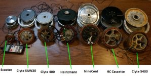
Motors On Table.jpg
 
And the results:
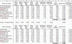
Heat Capacity Results.gif

I would say at best this is about +- 5% accuracy. We got a mean specific heat value of 0.499 J/gK for the motor cores (mostly steel and copper), and 0.588 J/gK for the motor shells (mostly steel and aluminum). The outliers are all outlying in the way that we would expect too. So for instance the Crysatlyte 400 front motor shell has a 9% lower specific heat than the average, at just 0.533 J/gK. But this was also the only motor tested that has an all steel rotor ring, with only the side plates being aluminum, and since steel has a much lower heat capacity than the same weight of Al it makes sense this would bring the effective average down. Similarly, those motor cores that had a cast alumimum stator support (9C30XX rear, Heinzmann, SAW 20XX etc.) had higher heat capacities than those with stamped steel stator supports (ex 9C 2800).

AND, finally we can see how the measured heat capacity numbers compare with the values I had derived from fitting the temperature rise plots with the model. In this post here, I had mentioned a heat capacity of 1400 for the 9C motor core, and 1100 for the motor shell:
http://endless-sphere.com/forums/viewtopic.php?p=718924#p718924

Meanwhile the measured results from this calorimeter test are 1200 J/k for the 9C 2800 motor core, and 1530 J/k for the motor shell. So the total heat capacity number is relatively close, but the division between the stator core and the shell is not quite the same.
 
Interesting tests, Justin :)

Taking at random your result for the 9C 2800 front motor core of 0.47 J/g/K at a weight of 2.545kg that should give us 1196J per °K temperature rise. Assuming an acceptable operating temperature of 100°C and 20°C ambient that gives us 80 x 1196 = 95.7 kJ or watt-seconds or 26.6 Wh.

Assuming I've added that up right it suggests that if we want to pour our 400Wh battery into the motor while running at 80% efficiency that's 80Wh of total heat input to the motor core, so heat shedding to atmosphere via the casing is required to handle the majority of the heat produced.

The average specific heat capacity for automatic transmission fluid for this temperature range is about 2.1 J/g/K at a density of 0.84 g/cc. For a typical 200ml put into a hub motor, this translates to 353J/K or 7.8 Wh for 80°C delta-T.

To me that suggests the main advantage of oil filling for cooling is better heat transfer to the casing and not simply increased thermal mass, as has been suggested before.

All assuming I added up correctly ;)
 
Hi, Every one. I have the first set of results to report for some experiments I am doing. I'm working on a project that I think many of you will be interested in. I have a few other ES members onboard to test out what I'm working on. Hopefully things will move allong quickly over the this weekend and the following week.

Here is a test of my H4065 without vents ability to shed heat:
[youtube]cqzVyiGRLj8[/youtube]

and graphed results:
H4065_No_Vents.JPG
ambient = 23.6
motor final = 58.9
diference= 35.3

watts/temp= 110/35.3
__________=3.12

the final temp may have eventually reached 60C so that would have made the watts/temp 3.02

more to come soon.

peace :)

Edit: note, I'm not accounting for inefficiency, however, for my experiment, I'll ignore it in future and the camparitive ratios will be relevant.
 
Punx0r said:
Interesting tests, Justin :)

Taking at random your result for the 9C 2800 front motor core of 0.47 J/g/K at a weight of 2.545kg that should give us 1196J per °K temperature rise. Assuming an acceptable operating temperature of 100°C and 20°C ambient that gives us 80 x 1196 = 95.7 kJ or watt-seconds or 26.6 Wh.

Assuming I've added that up right it suggests that if we want to pour our 400Wh battery into the motor while running at 80% efficiency that's 80Wh of total heat input to the motor core, so heat shedding to atmosphere via the casing is required to handle the majority of the heat produced.

Yup for sure, but it also says that you could dump say 50 wh of your battery pack in at 50% efficiency on a slow steep hill grind and not come close to burning the motor up. Not that 50 Wh is a whole lot of energy when it comes to climbing a long hill though.
The average specific heat capacity for automatic transmission fluid for this temperature range is about 2.1 J/g/K at a density of 0.84 g/cc. For a typical 200ml put into a hub motor, this translates to 353J/K or 7.8 Wh for 80°C delta-T.
To me that suggests the main advantage of oil filling for cooling is better heat transfer to the casing and not simply increased thermal mass, as has been suggested before.

That's true without a question, the purpose of transmission fluid is to get almost perfect heat transfer from the stator to the shell, not to provide more random mass to absorb heat, though as you calculated it does contribute a bit to that effect. When you do have a motor with fluid in it, then the core and the shell effectively become one single thermal mass, and since the results from our tests showed that the motor shells typically have more heat capacity than the motor core, adding the small amount of fluid will more than double the immediate heat capacity around the windings. So in a roundabout way it does increase the effective motor heat capacity much more than it's own small contribution would suggest.
 
pendragon8000 said:
Here is a test of my H4065 without vents ability to shed heat:

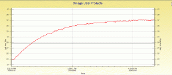
Fascinating. We've actually been using the exact same methodology for getting the thermal conductivity values for 3 different hub motors now, the small 20mm Crysatlyte SAW, the 9C 28XX, and the MXUS V2 45mm hubs. What we did is run the motors unloaded at 100, 200, 300, 400, and 500 RPM, using a CA to record the motor core temperature and the power going into the hub, and using an IR camera to monitor the shell temperatures.
MXUS_400rpm_Omega.gif

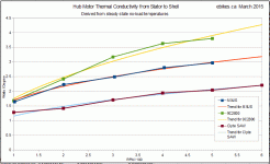
It generally took several hours before the motor was surely at steady state temperature, so to get lots of data points takes quite a while. Of the 3 motors tested, I was certainly expecting that the smallest motor (SAW20) would have the worst heat conductivity, followed by the larger 9C 2800, and finally the largest 45mm MXUS hub having the best. But the results showed consistently better thermal conductivity for the 9C motor than the MXUS hub, even though the MXUS has more surface area for shedding heat from the windings.

Preliminary Stator to Shell Conductivites Compared.gif

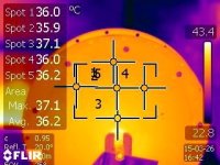
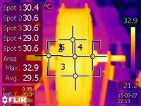
Here is an example of what the IR camera shot of a tested hub looks like immediately after the test is stopped. You can see that the temperature of the side plate is quite uniform over the entire surface, although it does get hotter near the middle (Spot3 is the furthest down). This MXUS motor has a cast aluminum stator core, which would mean that the axle has a very direct thermal path from the windings and so it's not surprising it would be hotter. I suppose that the center of the side plate also has the least air turbulence in this test and so wouldn't shed as much heat via convection to ambient.
MXUS_400rpm_IRCam.jpg

Here is the side view shot from a different tests where you can see that the axle is the hottest part visible.
IR Edge View.jpg

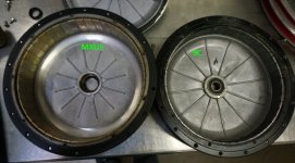
I thought that perhaps the reason the 9C motor did better at moving heat from the stator to the shell could be because it has more pronounced ribbing on the side plates going all the way to the perimeter which could act as vanes to help stir up air turbulence as the motor spins.

MXUS vs 9C Side Plate Ribs.jpg

We then did another test where we glued in a number of small cardboard vanes on the MXUS side plates, which helped a bit but still had worse conductivity than the narrower 9C, so there is something more at play here that I'm not getting.

the final temp may have eventually reached 60C so that would have made the watts/temp 3.02 more to come soon.

Yeah the temperature was definitely still going up when the test was stopped, but I'll look forwards to seeing additional data. Notice that your value of 3.02 W/degree is from stator to ambient, while the numbers in my graphs above is all from the stator to the side plate. The conductivity to ambient itself would be a fair bit worse.

Edit: note, I'm not accounting for inefficiency, however, for my experiment, I'll ignore it in future and the camparitive ratios will be relevant.

It's fairly safe to assume that at these low power levels, the almost all the 100 watts that you are measuring on the CA is winding up in the hub motor as heat. The I^2R looses in the controller mosfets and phase leads are really quite negligible when you only have a few amps flowing.
 
What is the intended purpose of the vanes by the engineers? Strength for the side covers?
 
Longshot said:
What is the intended purpose of the vanes by the engineers? Strength for the side covers?

Yes for sure, they are ribs rather than vanes, and without them the thicker boss for the ball bearing wouldn't be very well supported. Not all motor side covers have them (such as the Crysatlyte X5 side plates), but those that don't are usually a thicker casting.
 
justin_le said:
I thought that perhaps the reason the 9C motor did better at moving heat from the stator to the shell could be because it has more pronounced ribbing on the side plates going all the way to the perimeter which could act as vanes to help stir up air turbulence as the motor spins.


We then did another test where we glued in a number of small cardboard vanes on the MXUS side plates, which helped a bit but still had worse conductivity than the narrower 9C, so there is something more at play here that I'm not getting.
I don't pretend to understand thermal properties of things very well, but could the somewhat shinier machined surfaces on the MXUS's interior be causing reflection of some of the heat off teh windings back into them, instead of absorbed into it's surface, and affect your test in the way you see?

Or could the two covers be made of sufficiently different alloys to cause the difference in heat passage thru them?
 
Justin thanks for confirming I was on the right track with my calculations. here is the next set of results. I have drilled the side covers, the brake side - 19 millimeter holes drilled in the alcoves of they disk mount , and on the perimeter of the gear side plate I have drilled 18x 20 millimeter holes.
[youtube]upUdthnIuZg[/youtube]
Initial ambient temperature = 19.3°C
Final temp = 48°C
Temperature difference = 28.7
Power = 107watts (there were fluctuations but if you check my recording you will see its 107 watts most if the time leading up to the equlibrium temperature.)

This gives a watts/thermal of 3.73
Compared to the previousvalue for no holes of 3.02, showing a 24% increase.

I also turned on an industrial fan blowing over the wheel once it hit an equilibrium temperature, and measured the temperature drop. As you can see in the time lapse video , it dropped to 44.5, 3.5°c difference out of 28.7°c (Tmax-Tambient)

Im about to do my final recording and hoping for some good results.
Next post Ill show what I've been working on recently.
 
OK, final test:
[youtube]egDQnt8M4Vs[/youtube]

Here I have used what I am calling a U.D.I. - Under Disc Impeller.

the temperature got up to 39 C from 20 C and sitting on 100watts.

temp difference = 19 C

watt/temp = 5.26

This is a 24% increase on the drilled side covers without the impeller.

Basically the same increase again from un-vented to vented.

I used the industrial fan again and found it droped the temp by 1 deg C and then I bought it closer (right up to the wheel) and It went back up 1 degree C, so I used the higher of the readings ignoring the lower reading that would have given an extra good but maby false result.

heres some photos of the U.D.I
file.php

file.php


I've printed it with ABS because its UV stable and high heat tollerant.

Here is my for sale thread if anyone would like to buy 1 please PM me.
http://endless-sphere.com/forums/viewtopic.php?f=31&t=68373

Justin, if you would like me to donate one to test, I would be happy to.

cheers
 
amberwolf said:
justin_le said:
We then did another test where we glued in a number of small cardboard vanes on the MXUS side plates, which helped a bit but still had worse conductivity than the narrower 9C, so there is something more at play here that I'm not getting.
I don't pretend to understand thermal properties of things very well, but could the somewhat shinier machined surfaces on the MXUS's interior be causing reflection of some of the heat off teh windings back into them, instead of absorbed into it's surface, and affect your test in the way you see?

Or could the two covers be made of sufficiently different alloys to cause the difference in heat passage thru them?

thats what i also have thought. the 9C looks a bit darker so it probably will absorb more heat instead of reflecting it back to the stator.
brunishing or black anodizing of the entire inner surface would be optimal color for that. or very thin black painting (with a water-resistant marker). thats what i did on one of my MXUS motors.
 
Thanks Justin for these precious tests.. as well as doing them on the MXUS motor.

It would be really nice to make a test with Black body paint like the Krylon 1602 ultra flat mat black. Painting the inside of the cover as well as the outside wold make the aluminum to transfer radiant heat very well !

Otherwise bare aluminum or cast aluminum are just like a perfect mirror for the thermal IR... also black anodized aluminum is not better too.... it become like a real mirror from 800nm and above... !

I am using this high emissivity paint for various prototype of Thermal imaging system at work and it perform exactly the same as the popular Nextel Black velvet 811-21.

It absorb 97% of light and IR and absorb very well in far infrared as well as SWIR and MWIR. so the emissivity is near perfect.

The Krylon 1602 was discovered by the diy telescope astronomy community couple years ago.

It only cost 6$ per spray can compare to the Nextel. The Nextel cost 300$ per kit !! but both have the identical absorption spectrum including far infrared. It is just not low outgassing like some aerospaceproject require.. but i knwo the NASA are using it too. http://masterweb.jpl.nasa.gov/reference/paints.htm

Be aware that it is ONLY the Krylon 1602.. and not the 15602 or any other number... but it's the 1602 that have these performances

Once it is applied you will need to bake it in a oven for about 2h at 100 degree C.. once it is done the texture and black color will be just perfect.

Best%204%20paints%20MWIR.gif


5135.GIF


Here is some emissivity data: http://www.infrared-thermography.com/material-1.htm

Doc
 
John in CR said:
Why even bother talking about the minutia of using oil without talking about adding exterior surface area? It's absolutely required for a meaningful improvement good for all conditions. It matters little that heat can be transferred more readily from the stator to the shell if the same bottleneck at the outer surface of the shell remains. This limitation is why in the years since oil fill was introduced, that not a single person has used it to extract anything approaching extreme power from a hubmotor.

Well what if cooling fins are added to either the side covers and in between the spoke holes (like the middle of motor outside)? You could get an efficient cooling surface "like a football field". Also what if an impeller is added to the side cover? Then you add your "cup of oil" inside the motor, after tinning the wires to avoid wich, using loads of epoxy and thermal coating/painting the inside of the hub.

 
fellow said:
Isn't is easier to add the external oil radiator and a small electric pump (car and motorcycle junkyards are full of it) than adding the alu sinks outside the rotating hub? MXUS3000 (3kW air cooled, 8 kg) is only about the twice cooling area vs small Q100H (good for max 1 kW oil cooled, 2 kg). We need something about 10 times bigger area. Sooner or later we must accept motorcycle cooling soulutions (big radiator, fluid cooling) as the only way of getting into the 10+ kW terrirory.


Yes I think that would the best way to really push the limits. But I also think it would require a custom made cooling block that would be placed inside the hub. Most likely it will require custom made axle and larger bearings as well. I think if we could do a proper 3D drawing of such a system we might be able to get ie QS to make a batch of motors to specs. At least if we would make a large group buy. There would be no need for oil filled hubs that leaks. And you could increase the size of radiator if needed. Also this solution would be suitable with many other mods like large surface cooling fins and impeller fan.

Here is one solution,
500x1000px-LL-1756ccf7_internal1.jpeg


Personally I would prefer a custom cooling block covering all the black parts(stator?) of the pic below. Imagine we make a 3D drawing that also contains cooling fins for side covers and the space between the spoke holes. That would be the ultimate cooling solution. If we are to get a big enough group buy I am certain a vendor would do a custom batch of motors for us.

500x1000px-LL-4d2d689a_Wheel_motor_small_.jpeg


It might not be sufficient as people have pointed out before, but if we could combine such a solution with ie outside cooling fins I think
 
madin88 said:
amberwolf said:
I don't pretend to understand thermal properties of things very well, but could the somewhat shinier machined surfaces on the MXUS's interior be causing reflection of some of the heat off teh windings back into them, instead of absorbed into it's surface, and affect your test in the way you see?

Or could the two covers be made of sufficiently different alloys to cause the difference in heat passage thru them?

thats what i also have thought. the 9C looks a bit darker so it probably will absorb more heat instead of reflecting it back to the stator.
brunishing or black anodizing of the entire inner surface would be optimal color for that. or very thin black painting (with a water-resistant marker). thats what i did on one of my MXUS motors.

This is a good question/observation that we hadn't considered too much because I had been assuming that most of the heat transfer in the casing would be convective and that radiation would be a minor factor. For these particular tests, we were running the motor unloaded at only like 20-30 watts of heat input, so the motor core and shell temperatures were comparatively low.

But we've now started repeating the tests on the 9C motor using a field oriented controller to produce 20 amps of field weakening current in addition to the 1-2A of drive current, and so now we are dumping in like 150 watts of heat in the stator so that the core is now upwards 100-120 oC, and radiant cooling could be much more significant. It'll be really easy to paint the insides of each side cover (thanks for the paint tips Doctrobass!) and see how that changes things. IIRC from back of the envelope calculations it was expected to be on the order of 10-20 watts of radiation at normal ebike power levels and operating temps.
 
Yes, please paint the inside of the covers flat black and measure before and after. Any old flat black paint. It actually can make a huge difference in a sealed enclosure and the shiny unfinished aluminum acts like a box lined with mirrors on the inside walls. In one experiment (not a motor) I saw a 15C reduction in internal ambient simply by painting only 4 of the 6 walls inside a rectangular enclosure.

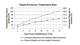
Here is data from a sealed electronics enclosure:

paint.PNG
 
BUt it is also important to paint the outside too!

Aluminum will radiate the heat easier with black color on the outside!

The best black body is also the best emitter too!!

Fathill.. not all black paint have the same emissivity and not the same spectrum of emissivity.

I have tested that at weok for a project... the Krylon 1602 IS the real flat black mat!!

Also painting the entire motor core would be great !! including the winding!.. so this way nearly ALL the radian heat would exit the motor shell.

That paint is for radian heat like copper is for current !!


Doc
 
Doctorbass said:
Cowardlyduck did it nicely too with the HS4835 but he forgot to paint the outside of the motor.. maybe was it for aesthetic preference
:mrgreen: Lol :lol: That was just because it was the only paint I could find at the time that would handle high temps...had no idea about it's thermal transfer characteristics...but win! Shame I don't have that motor anymore...after selling it due to winding damage, it turned out to work fine.

For my latest motor project I've done this though. :)
P1070447.jpg

Was freakin hilarious as it made Kiriakos GR cry and leave the thread when he failed to understand why I wouldn't paint it white like he suggested.
http://endless-sphere.com/forums/viewtopic.php?f=30&t=56965&start=150#p1012106 Apparently because all the roofs and outdoor appliances in Greece are white, so should the insides of our motor's according to him. :lol: :roll:

However I did paint my windings with red insulating varnish to protect them from the elements.
P1070421.jpg

Do you think it would it be worth going over the top with some matt black now, or would the extra layer of paint be more thermally insulating and not help?
I might paint the outside of the side covers as suggested this time around though as that makes a lot of sense.
Thanks for the tip Doctorbass. :)

Cheers
 
Interesting. Thinking of testing the coating on my latest shipment of mxus hubs.
 
Any flat black paint will do. The the difference between the best and worse is very very slight, compared to the huge difference between raw and flat painted. It is actually more important that you only use a light coat.

Painting the outside does not make much difference at all, but painting it black on the outside will make it get hotter sitting in the sun as it absorbs IR.

If your hub is vented painting the inside wont make much difference. For sealed enclosures, painting the inside flat black makes a huge difference, 15C in my non motor application. I was really suprised myself. It has to be because the IR emitted from the heat source is reflected multiple time inside the enclosure by the walls, each time it reflects a little more is absorbed, while on the outside it is only emitted once. So inside the black paint does a good job of both emitting AND absorbing IR. That is my theory anyway as to why I see such a huge difference.

Try it yourself and measure the difference one change at a time
 
flathill, im with you.

the color of the paint almost does not matter for heat EMISSION, but i believe only at the temperature levels of our motors.
so if the stator and windings are painted white as example, it will not be noticeable poorer than black. it only is important that the color is matt and not shiny as already mentioned.

for ABSORBTION, color makes a huge differences. so you definitely want to have the inside of the sidecovers black while on the outside white will be better because it does not absorb heat coming from the sun or environment..

Doctorbass said:
Otherwise bare aluminum or cast aluminum are just like a perfect mirror for the thermal IR... also black anodized aluminum is not better too.... it become like a real mirror from 800nm and above... !
Doc

thanks for this info. so that means it's not a good idea to use black anodizing for heat absorption, but for heat emission it will do a very good job (just like any color will do), right?
the reason why i would prefer anodizing or brunishing is it does not act as an insulation (like paint will do) so heat transfer to moving air will be better.
 
pendragon8000 said:
OK, final test:
[youtube]egDQnt8M4Vs[/youtube]

Here I have used what I am calling a U.D.I. - Under Disc Impeller.

the temperature got up to 39 C from 20 C and sitting on 100watts.

temp difference = 19 C

watt/temp = 5.26

This is a 24% increase on the drilled side covers without the impeller.

Basically the same increase again from un-vented to vented.

I used the industrial fan again and found it droped the temp by 1 deg C and then I bought it closer (right up to the wheel) and It went back up 1 degree C, so I used the higher of the readings ignoring the lower reading that would have given an extra good but maby false result.

heres some photos of the U.D.I
file.php

file.php


I've printed it with ABS because its UV stable and high heat tollerant.

Here is my for sale thread if anyone would like to buy 1 please PM me.
http://endless-sphere.com/forums/viewtopic.php?f=31&t=68373

Justin, if you would like me to donate one to test, I would be happy to.

cheers

love your work mate, any notable increase in no-load power use?
and its considerably more effective than 'twice the vented cover' - as the lower delta t between vented with fan and ambient vs just vented makes heat extraction even harder. it'd be great to see some higher power tests, particularly how much more cont. power you can push with the fan vs un-vented. Shit mate, I wish I had more time - would love to come over and lend a hand with such tests!
 
Back
Top