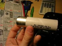
Eric's Project #002

The EB series sla's from B&B put out 75% of rated capacity. An EB-20ah 12 volt battery has 15ah. Its only $56 but probably won't fit in your box too good. Its supposely good for 500 cycles. Dimensions 7x3x6.5
They only make 3 sizes. A 12ah, 20ah, and I think a 50ah. I would figure a way to make them fit and save the dough.
 
D-Man said:
The EB series sla's from B&B put out 75% of rated capacity. An EB-20ah 12 volt battery has 15ah. Its only $56 but probably won't fit in your box too good. Its supposely good for 500 cycles. Dimensions 7x3x6.5
They only make 3 sizes. A 12ah, 20ah, and I think a 50ah. I would figure a way to make them fit and save the dough.
Its too late for all that. I downsized my battery box about an inch in each direction in anticiaption of using lithium. I don't think I can change my mind at this point.

Thanks for the tip on BB batteries. I might get those for my current scooter.


I'm scouring the internet trying to find info on discharge rates of these emoli, milwaukee batteries. The only thing I've found is at falconev.com who say their LiMn batteries have a max of 3c.

I'm think I'm going to need about a 2.5C max rate, so I can discharge at a slower rate about 1.5c so I don't strain the batteries. Also, as the batteries age, they won't be able to produce as well, so I need some buffer to account for that.

I"d like to get this type of set-up:

Batteries = 21ah @ 54v
Discharge rate = 1.2C
Power = 25amps @ 48v = 1200 watts (using sag=6v)

OR

Batteries = 18ah @ 54v
Discharge rate = 1.4C
Power = 25amps @ 48v = 1200 watts (using sag=6v)

How do these numbers look? I know SLAs are only really good for about 1.5C. What about these? SHould I try to get more batteries onboard? If I had to I could fit them into the neck.

What is a good discharge rate?
 
Beagle123 said:

I'm scouring the internet trying to find info on discharge rates of these emoli, milwaukee batteries. The only thing I've found is at falconev.com who say their LiMn batteries have a max of 3c....
What is a good discharge rate?

Emoli's are good for 20C burst; 15C max continuous; 10-12C without breaking a sweat. See:
http://www.swift-tuning.com/EMOLI_26700A.pdf

I don't think you have any worries in this regard. A well-wired 6p emoli pack will provide 270 amps continuously. :)

There's much more to maximum discharge rates than just the battery chemistry, though the battery chemistry sets the upper limit of drainrate possibility.
 
You might also want to look at the emoli pack build instructions and videos here:
http://www.swift-tuning.com/e-moli.php
 
Did you not look at the links on the previous page, TD? An emoli cell is good for 45 amps (15C) continuously -- many RC people run them at 45 amps, but report best performance at 30 amps or less (per cell in parallel).
http://www.swift-tuning.com/EMOLI_26700A.pdf
 

I get it. thanks guys. I found something for you xter. You know how you're always saying, "I'm going to cut the tabs and fold them over so I don't have to solder my batteries etc."

What about this:

http://www.intek-uk.com/condepox.htm
http://www.electronix.com/catalog/product_info.php/cPath/3/products_id/17697

 
Beagle123 said:

I get it. thanks guys. I found something for you xter. You know how you're always saying, "I'm going to cut the tabs and fold them over so I don't have to solder my batteries etc."

What about this:

http://www.intek-uk.com/condepox.htm
http://www.electronix.com/catalog/product_info.php/cPath/3/products_id/17697


I rebuilt my present pack by folding the tabs over the wire, crimping, and then soldering. I plan to do the same for my next pack too (as in still solder, but also cut the tabs linking the emoli cells in the middle so I have the tabs to fold over the wire). I'm interested in these conductive pastes as an alternative to solder; but I was hoping to see somebody else here try it first. I've got all the soldering equipment already, and plenty of patience, so soldering is no big deal to me. The tabs on emoli's and A123's are quite wide; it may be possible to create a permanently patent connection simply by crimping the wire between the folded tabs in multiple places on each tab, then taping the tabs back against the cell to hold everything together with the springy tension in the tabs -- no solder or paste.
 
Thinking about Alternatives to My Plastic Battery Box Idea

I wanted to make plastic boxes with a strip of metal along the top and bottom to make my battery sub-packs. I was hoping to make them hold in place with friction like in most electrical devices. I wanted the ability to take out the cells, adn test them removing bad ones.

Do you guys think I should worry about that? I've read xter's posts about encountering a bad cell, and it inspired me to think about the best solution to managing hundreds of batteries. I beleive its a mechanical connection which can be completely tinkered with.

Another more simple approach occured to me-- I could use this conductive glue to hold the parallel packs together. I could lay the batteries in a row, put a drop of glue on each top and stick a metal bar across all the tops. Attach a terminal wire to each top and bottom, and you;ve go t 6 parallel sub-battery pack.

The row of batteries should be glued in a neat line, just attach the terminals to it and cover it in plastic.

It would also eliminate my space concerns because the thickness of the plastic boxes was making it a tight ffit. THere will be plenty of room without them.

So, what would the plan be down the road? If I start getting less performance, I could easily take out a subpack and examine the whole thing. But if there was a bad cell in there, I'd have to rip it apart.

Or, I could throw it away and replace it.

THe downside to this is that all the batteries are trapped in these cases, so if any go bad, they'll rot in there for a while.

Is this a real concern/?

Should I just bond the packs together,?


[/size]
 
A Few Calculations

If xter's chart is correct, my batteries can operate at virtually unlimited discharge rates. It would certainly be limited by my controller's max rate of 100amps. in my 18ah pack, 100amps = 5.5c discharge rate. According to the charge chart, the batteries would sag a volt or two.

So in the end, My batteriess could deliver 100 amps @ 54 volts. That's 5400 watts! That's 7.2 horsepower

And that is what is supposed to happen if I open the throttle to full.

I may need a smaller controller.

But if I got a hub motor like xter's and put it on the front wheel (on a 28 inch wheel), then I could run 4000 watts in the back, and another 4000 in the front. that would only be about a 10C discharge. I think it would break some speed records at that point.


you'd have to use a low winding number otherwise i reckons you'd hit max speed on the hubmotor! :)

this is shaping up to be an awesome project! keep up the good work Eric.

Take Care,
Haydon
 
Beagle123 said:
Another more simple approach occured to me-- I could use this conductive glue to hold the parallel packs together. I could lay the batteries in a row, put a drop of glue on each top and stick a metal bar across all the tops. Attach a terminal wire to each top and bottom, and you;ve go t 6 parallel sub-battery pack.

There's the glue approach and the paste approach, both exploit silver or something silver like to get a better electrical connection than soldering. Glue is an interesting thought... my #002 bike has the idea of packing the batteries inside the frame tubes and then simply holding them together with a tight spring. I think that ANY rigid connection will be subject to stress and possible failure over time. By keeping things tightly pressed together, but not rigid, you eliminate the possiblity of things failing as a result of the bike bouncing around.

Xyster seems to have found an interesting combination of a rigid solder joint combined with flexible connector wires. That looks to be a winning idea.

The "totally rigid" pack demands that all the batteries are held very tightly together (usually with a wrap of some sort) and that amplifies all the heat related problems as well. So the traditional pack appears to suffer from a range of ills that work against you.

Is there any way to place rows of cells into tubes? Maybe PVC pipe with holes drilled in them and springs on the ends. There was one guy that did that and other than the fact he forgot to use springs (he tried to use a screw joint which didn't react to expansion related to heat very well) it worked okay.

:arrow: Paste or Glue or Solder?

So many choices...
 
Beagle123 said:
So in the end, My batteriess could deliver 100 amps @ 54 volts. That's 5400 watts! That's 7.2 horsepower

And that is what is supposed to happen if I open the throttle to full.

I may need a smaller controller.

Nonsense :twisted:

My little BMC motor sucks up over 100 amps at 60v. It won't stay at this level long as you accelerate (or get tossed off the bike). That's what makes it fun.

You could add a current limiter like Mr. Electric (I think he was using the same controller). The new CA has that feature built in, so would be a good alternative.
 
Beagle said:
Do you guys think I should worry about that? I've read xter's posts about encountering a bad cell, and it inspired me to think about the best solution to managing hundreds of batteries. I beleive its a mechanical connection which can be completely tinkered with.
safe said:
Xyster seems to have found an interesting combination of a rigid solder joint combined with flexible connector wires. That looks to be a winning idea.

Beagle, with modularity and easy cell replacement in mind, I've experimented with many different cell connection methods. If I was you, I'd do it the way I'm doing it now: Get some ultra-flex noodle wire -- 12ga for the main wires and 18 or 20ga for the charging wires:
http://cheapbatterypacks.com/main.asp?sid=840481&pgid=wire
Coated with silicon, this noodle wire is also MUCH easier to strip than other wire.
Then, like in the pics below, fold the tab over the wire and crimp -- with a crimper if you can fit it in there, or press down with the tip of a screwdriver. After your pack is tested, then solder across the tops of the tabs and wires. I use silicon glue between the batteries because it's strong enough, yet peels right off.

I'd also load-test each cell first by connecting it to parallel'd resistors and measuring the voltage drop (see third pic down). I haven't read of an Emoli or A123 dying while in use under normal-ish operation. Approximately 1 in a few hundred cells seem to be DOA, however. So if you can test each cell first, you should be safe to solder the pack prior to in-bike testing.


3_160.jpg


4_160.jpg


Load testing an Li-ion 18650:
1_160.jpg
 
Xyster has created a "hybrid" battery solution that is both flexible and solid at the same time. In this area I have to say he's got a very good idea. It looks like the most reliable option of the "known" ways of doing things. I'm venturing into uncharted waters with the spring loaded battery, though things like flashlights have been using the idea for years.
 
xyster, you have the same multimeter as me, the one with the battery the size of a peanut that costs $5(sold separately), and after opening you will never be able to close it again unless you have a magic robot organize the leads into the right shape.
 
dirty_d said:
...you will never be able to close it again unless you have a magic robot organize the leads into the right shape.

:D I noticed.
 

Lots to cover:

Hayden: Thanks. I'm not using a hubmotor. I finally settled on the Unite 1200w 48v one.


Safe:


The "totally rigid" pack demands that all the batteries are held very tightly together (usually with a wrap of some sort) and that amplifies all the heat related problems as well. So the traditional pack appears to suffer from a range of ills that work against you.

Yea its a tradeoff. I'm going to test the glue. If its really strong, then I may have to use it. Unfortunately that would mean that my packs are permanently bonded together, so I couldn't take out batteries when they go bad. I'd have to throw-away the whole pack.

I think the packs should hold together fine because there won't be forces to break them apart. Also, I'm planning on having my packs be a single row of batteriess standing on its end, so rigid might be better for me. (see pics). It all depends on how good the glue is.

Fetcher: Yea, that little scooter of yours screams. I still can't understand how you get those little SLAs to put out 60 amps. I wanted to get your motor set-up, but the only thing that deterred me was the RPMs. I can't handle 5000 RPMs. I"d love to make a ultra-light bike with that motor though.

Hey wait. 100 amps at 60 volts is 6000 watts! I can't beleive that thing's putting-out 6000 watts! (8 hp!)

I'm drooling right now. I want to try my new bike!

Xter
12ga for the main wires and 18 or 20ga for the charging wires:
I'd prefer slightly bigger wire for the main. I just made my charging wires out of 22-23 ga. I think that's fine because its similar to the charger's wires.

Then, like in the pics below, fold the tab over the wire and crimp
I can't do anything with tabs because there aren't any. The battery looks like smooth stainless steel everywhere except where the spot welder connections are. See pic.
I use silicon glue between the batteries because it's strong enough, yet peels right off.

I don't beleive this is an option either. These cells aren't like yours. These are encased in a paper wrapper. (see pic) If you glued them together, you'd just be gluing the paper together. I think the paper is to insulate the cell because the negative end is completely connected up the sides of the battery up to the top. If you took the paper off, you'd expose the negative terminals. This could be dicey if the positive wire touched anywhere on the pack.
I'd also load-test each cell first by connecting it to parallel'd resistors

What are you using as your resistors? I have a electrical experiment kit with a bunch of resistors in it. Can I use that?

I tested each battery's voltage. All were exactly 3.85v

Thanks for all the great advise.

So I assume that you aren't in favor of my gluing idea because I can't dismantle it an test/replace cells?
 

Attachments

  • DSCN0601.JPG
    DSCN0601.JPG
    47.5 KB · Views: 2,198
Soldered Charging Wires, Neck is Being Welded. First Charger Arrived

Only a little to report today. The frame is at the welder's shop now, so no pics of the neck being welded.

My first charger arrived today. It looks great. I should be able to fit 14 of them in the neck portion of my frame (onboard charging). It should be a very neat set-up. I ordered 15 more chargers.

Chargers:
http://www.batteryspace.com/index.asp?PageAction=VIEWPROD&ProdID=1231

I soldered the charging leads. I'm using Dean's micro plugs as connectors (Patrick's tip). They're tiny little plugs that are perfect for small guage wire. I'm not great at soldering, but once I learned to clean the tip (first with sandpaper, then with tip cleaner) it started to go more smoothly.

The 14 wires pictured below will be the charging leads coming from each battery pack. When I get the charger, I'll connect the other end of the plug to each one, so each charger will plug into one battery pack.

There are also pictures of the battery set-up I'm considering. The aluminum tread-plate would be glued across the terminals of the batteries. Everything would be wrapped in gorilla tape to insulate it. I guess those would be PERMINENT battery packs.

 
Beagle123 said:

Lots to cover:
Xter
12ga for the main wires and 18 or 20ga for the charging wires:
I'd prefer slightly bigger wire for the main. I just made my charging wires out of 22-23 ga. I think that's fine because its similar to the charger's wires.
OK. I couldn't find noodle wire in sizes bigger than 12ga. However, by sending a lead out both ends of both sides of a subpack, the current is flowing through two 12ga leads instead of one -- which provides almost the same resistance as a single 10ga wire.

Then, like in the pics below, fold the tab over the wire and crimp
I can't do anything with tabs because there aren't any. The battery looks like smooth stainless steel everywhere except where the spot welder connections are. See pic.

All the pictures of emoli packs I've seen, including the one below, show tabs. Are you saying your pack is constructed differently than this:
http://www.swift-tuning.com/emoli.pdf
emoli_tabs_118.jpg

?

Also, gluing an aluminum treadplate to the cell terminals sounds like a sketchy connection at best.

I use silicon glue between the batteries because it's strong enough, yet peels right off.

I don't beleive this is an option either. These cells aren't like yours. These are encased in a paper wrapper. (see pic) If you glued them together, you'd just be gluing the paper together. I think the paper is to insulate the cell because the negative end is completely connected up the sides of the battery up to the top. If you took the paper off, you'd expose the negative terminals. This could be dicey if the positive wire touched anywhere on the pack.
I'd also load-test each cell first by connecting it to parallel'd resistors

I agree the paper is to insulate the cells. I'd still use silicon glue on the paper, then wrap each subpack with tape. But there's more than one way to skin this cat, obviously.


What are you using as your resistors? I have a electrical experiment kit with a bunch of resistors in it. Can I use that?

I tested each battery's voltage. All were exactly 3.85v

Thanks for all the great advise.

So I assume that you aren't in favor of my gluing idea because I can't dismantle it an test/replace cells?

Probably all cells testing around half-full (3.85v) when new are OK. So load testing is just an option. I forget the resistor size I used -- I think it was 4, 10ohm resistors in parallel to make one 2.5 ohm resistor). Anyway, I used Ohm's law to find the resistance I needed to drain 1-2 amps from my cells; then I paralleled power resistors I bought from radioshack. You could do the same to test the cells at a higher drain-rate. Regular, little resistors will fry -- you'd need to use something like 10W power resistors.
 
xyster said:
OK. I couldn't find noodle wire in sizes bigger than 12ga. However, by sending a lead out both ends of both sides of a subpack, the current is flowing through two 12ga leads instead of one -- which provides almost the same resistance as a single 10ga wire.

You might also consider checking-out the cable for badass audio setups.

http://www.lightav.com/car/phoenix/install.html

:?:
 
TylerDurden said:
xyster said:
OK. I couldn't find noodle wire in sizes bigger than 12ga. However, by sending a lead out both ends of both sides of a subpack, the current is flowing through two 12ga leads instead of one -- which provides almost the same resistance as a single 10ga wire.

You might also consider checking-out the cable for badass audio setups.

http://www.lightav.com/car/phoenix/install.html

:?:

Probably ridiculously expensive and not ultra-flexible high-strand-count noodle wire. I can always double/triple up on the 12ga if I needed to.
 
All the pictures of emoli packs I've seen, including the one below, show tabs.

Yes your pictures show the same pack as I have. However, its difficult to preserve the tabs. They are spot welded very tightly to the batteries. Its hard to get a screwdriver under them, and when you do, you can easily break a spot or two on the welds (there are 4 tiny spots on each tab that is welded to the battery.

Notice that on the picture, the tab is broken off.

You might be able to preserve them using a dremel with a cutoff wheeel. You'd have to cut it from the top.


Also, gluing an aluminum treadplate to the cell terminals sounds like a sketchy connection at best.

I totally disagree. This glue conducts electricity very well. The resistance number I saw was .001 ohm. They also sell conductive epoxy. Keep in mind that expoy is used to adhere golf club heads to the shafts (sounds strong to me.) The aluminum treadplate has much less resistance than 10 ga wire. I think this set-up will have huge capacity to conduct electricity.

And keep in mind that my opinions count more because I write in bigger letters.


I agree the paper is to insulate the cells. I'd still use silicon glue on the paper, then wrap each subpack with tape. But there's more than one way to skin this cat, obviously.

Another benefit of the treadplate/glue system is that the metal and glue will hold the cells together without additional glue.

I know your set-up works well, and one of the biggest advantages of it is that you've verified that it works well. Also, I'm in total agreement with you about the electrical set-up. But, I'm still "on the fence" about the physical set-up.

I'm asking the question, "What if I could make one big permanent battery from 7 cells?" It seems like if a battery was available that was 3.7v, 21ah, we'd be so happy, we'd piss in our pants. That's what I'm talking about doing. I can't see much downside to having one big cell. If cells start to go bad, its no big deal--I can just test each pack like you suggested without even taking them out of the bike! It would just cost me $100 to replace a pack. I imagine that will happen in the next year or two.

Suppose that one cell in the pack starts to go bad. Would that be a major problem? It seems like the other cells would continue to make the pack function fine. When 2 or 3 cells go bad then the pack would drain too rapidly, but I could test each pack's voltage (after a ride) every month or two. this would be easy--take off lid, disconnect aandersen connectors, use voltmeter.

Wouldn't you love it if you could buy a 3.7v, 21ah battery?


Back
Top