Eric's Project #002

It's like you need something that will hold all the batteries in place without them touching each other in a line for a subpack, so you can run wire to charge them individually. Then use something that is insulated except for specific contact points that slides into(and out of) place to make the connections between the batteries to the full voltage.


If not between every cell then perhaps between clusters of cells (say 12 volt packs? so standard car charges can be used). Also if the subpacks are modular design they can be swapped out quickly. Once swapped out easily taken apart to test cells.
 
Hi Lesss:

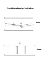
I totally agree. I was thinking about a hardware switch like the one pictured below. I think there's a better way.

I bought a power supply to charge my batteries today:

<a href="http://cgi.ebay.com/ws/eBayISAPI.dll?ViewItem&rd=1&item=290174751148&ssPageName=STRK:MEWN:IT&ih=019"> 0-10v, 50A power supply</a>

I'll be charging at about 0.16C with 50 amps. Charging time will most likely be about 3-5 hours.

I was considering a 400 amp model too. A couple of these could charge an electric car:

<a href="http://cgi.ebay.com/ws/eBayISAPI.dll?ViewItem&rd=1&item=300148554794&ssPageName=STRK:MEWA:IT&ih=020">4-6v, 400A power supply (240vac input)</a>

There are a million 5v, 50-100 power supplies available very cheaply (like $20-30). If anyone knows how to make them put-out 4.2v, you could make a really big charger.

I may still buy the 400 amp one and use it to charge my bike faster. Also, in the future maybe I'll have a bigger/better battery going.
 

Attachments

  • seriesparallel.jpg
    seriesparallel.jpg
    11.2 KB · Views: 3,514
Hmm... I think that the general concept might work, but I'm curious to see the switch that would do the trick 'in real life'.

I've never seen a mechanical switch that would work, considering the number of poles and the amount of current handling that would be necessary. I suppose you could build one, but if I had to build one, it would be about half the size of the bike.:shock:

Unless I'm missing something (which is quite possible..... I start getting confused at anything more complicated than a DPDT switch wiring.)

You could do it with solid state relay switches, in about the size of a shoebox (which is still too big for a bike/scooter), but that would be rather expensive even if you found a good surplus source.

Scanning back through earlier pages, you mentioned using MOSFETS for switching ; I don't know enough about them to comment; did you get any more solid info on how that would work? I think you could do it with reasonably priced SCRs, but wiring would be a rats nest, Even if you could use printed circuits as much as possible, I think.
--------------------------------------------------------
SOME of those cheaper, beefy regulated power supplies have (or at least the older ones had) an adjustment screw that would allow you at least 10% +, and I had an old 48V one that would adjust up to 20% up or down, so it MIGHT be possible to find a 5V one that wouldn't require modification to put out 4.1V or 4.2 V. I'm not sure how well the regulation works when adjusted toward the nether limits though.
-------------------------------------------------------------------------------------
On a related note, I have made some progress with my home built sub $100 battery tab welder projects.

The AC one wasn't a complete failure, but I wouldn't want to try it on ANY size Lithium battery, or anything smaller than a D cell in NiMH... although it does weld tabs on the D cell sized batteries with slightly less abuse than soldering. The one old LiIon 20500 battery I tried it on didn't explode or anything, but it will never be safe to have around the house again.

The capacitive discharge welder shows surprisingly good results sometimes on any of a variety of cells, but occasionally doesn't make a good solid weld. I just bought a few different components off eBay to see if I can tweak it into more consistent and slightly deeper welds before I write it up and make it public. But it is definitely 'doable' for around a hundred $ and can be made into something fairly elegant if not pretty enough to sell commercially, for about twice that.
 
I've seen quite a few surplus 5v power supplies that can really crank out the amps. Even a used computer power supply can put out a lot. There should be some way to change a small resistor in there to get 4.2v instead of 5v. Finding the small resistor could be challenging and would vary with model. Any power supply with a voltage trim adjustment would be easier to hack, since the adjustment is obvious. If the pot does not provide enough range, it is easy to extend the range by adding a resistor in series with one side of it.

I assume from your description that the AC welder causes too much heating of the cell.

Perhaps if the welding current were increased, but the duration decreased it might work better. I guess this is what the CD welder does.

How big does the capacitor need to be for a welder?

What kind of transformer did you use for the AC welder?
 
Fechter; I don't want to hijack Eric's thread, but the short version is:

AC: Rewound microwave oven transformer. Heating can be a problem depending on your technique, but it is less heating of the internals of the battery that bothers me than just 'blasting' through the thin metals of the terminal when the voltage is high enough to do a quick weld: 3.5-4.2V gives the nicest welds, but requires a duration that gets the guts too hot. 5.5V is quick enough to weld without heating up the guts, but every third or fourth weld will blast through the 'shell'.
And inconsistency is a problem no matter what voltage.; one of those fraction of a second timers might do the trick, but I wanted to avoid that if possible. Going DC might help too. I made a 200A , CPU fan cooled, bridge rectifier, but haven't tried it on the AC welder yet.

Part of the problem could be that our line voltage is not well regulated; we vary from 110 to 125.7 V at any given moment.

CD: Since I can't find any good electronics caps at a reasonable price to put in a parallel array like I did on the one I built years ago, I just settled for a car audio super cap of 1.5 farad. I don't know how long they will last with this application, but it definitely will work. Just ordered a 3 farad unit to see if it will give slightly deeper welds at 12V, or tolerate higher voltage better. The 1.5 F blew its seal and vented when I pumped 18VDC at pretty hefty amperage into it (Supposedly it is OK on 20 V with 24 V surge, but reality didn't match its advertising) (still works though ;) )

I still believe that either approach can be made to work well enough for hobby use without spending much, but I'm trying to make it possible to build one for less than a hundred dollars even if you have to buy everything for it off eBay, and at your local hardware, Walmart and RadioShack stores. (That is the one thing I miss about living in Phoenix AZ. At Davis Salvage and Scrap I could get everything I need to build a super unit for fifty dollars or so.)

I'll write all this stuff up, with diagrams, photos and even videos and post it in a dedicated thread here in a week or two, and quit hijacking other peoples threads. (Apologies again, Eric)
 
Hi RLT:

You could do it with solid state relay switches

I considered that, but they have more resistance. I wouldn't want to use 14 of them in my ciuruit.

you mentioned using MOSFETS for switching ; I don't know enough about them to comment; did you get any more solid info on how that would work?

I decided against MOSFETs. They also have some resistance. Also, I don't like the idea of having the connection controlled with electronics because its invisible to me. I want to physically see that it is disconnected becasue it could be a major problem if its still connected. That's why I prefer my "idiotproof" solutions where you must unplug the batteries to plug in the charger. Stay tuned. In about a week, I'll post pictures of my solution. I'm confident it will be really good.

I posted a picture of a switch below that could work. I have other designs as well.

That's really cool that you cn make a welder. I'd love to see a weld on a battery.

Hi Fetcher:

I'm telling you that these surplus power supplies are really cheap. THe really impresive one is the 400 amp one. And it doesw adjust to 4.2v.

Also, I don't care if you hijack this thread. I've had a lull in the action lateley. However, I will be getting my batteries next week.

 
oh! OK!
I can now see how that might work. Nice 'outside the box' thinking. Not sure I'd enjoy trying to build one myself, but a better craftsman than I could definitely build one that would handle any current necessary, and do it relatively compactly.

My ('pseudo) D cell' 5+AH LiIons are supposed to be here from Hong Kong in 5-7 days if they don't get hung up in Customs; So I'm going to have to get my act together pretty soon too. Although they are really intended for my # 2. or maybe, now, # 3 project, (a semi- stealthy, mountain trail bike which is still in the 'thinking about' stage.)
 
It would be nice if there was an off-the-shelf switch that would do that. I can't think of anything I've seen.

One thing to be careful of is to make sure the switch can't short a cell when it's half way between positions. Break before make, or something like that.

Since the switch doesn't need to switch under load, the contact material could be any good conductor. Perhaps something like a many pole Frankenstien knife switch would work.

Personally, I still don't like the idea of all those contact points that can develop high resistance later on.

400 amps?! Wow, you'd need welding cable for that one.

OK, it can double as a charger and a battery tab welder :p
 
That's a very interesting series/parallel switching system idea, but I don't see how it disengages the series wiring when it engages the parallel wiring (which I do see). Can you expand on this, Beagle?
switch_801.jpg
 
Hi RLT, fetcher and xter:

I'm not sure how to explain how the wiring for the series connection disengages because there is no wiring. The battereis are just connected to the contacts. As long as pluses are touching pluses and minuses touching minuses the series connections must be disconnected.

Actually, this isn't the best version. I like the idea that I'm going to use with the andersens connectors better.

I think xter is prime candidate to use this system. Since he uses a 33 ah pack. To charge a 33ah pack at 0.5C, it would take 330 amps at 4.2v. The normal charging time would be about 1 1/2 hours. This charger would be perfect (if you have a 220v outlet):

<a href="http://cgi.ebay.com/ws/eBayISAPI.dll?ViewItem&rd=1&item=300148554794&ssPageName=STRK:MEWA:IT&ih=020">400 amp charger</a>
 
Beagle123 said:

I think xter is prime candidate to use this system. Since he uses a 33 ah pack. To charge a 33ah pack at 0.5C, it would take 330 amps at 4.2v. The normal charging time would be about 1 1/2 hours. This charger would be perfect (if you have a 220v outlet):

<a href="http://cgi.ebay.com/ws/eBayISAPI.dll?ViewItem&rd=1&item=300148554794&ssPageName=STRK:MEWA:IT&ih=020">400 amp charger</a>

I really have no need to charge that fast. My present system fits my needs more than adequately. So it's just not worth the time or money to me to rebuild my pack to charge from that.
Sounds like it could work well for you though, Beagle. :) Do you have 220v large appliance outlets in your house?
 

Yea, I have a 220v outlet in my living room. We should try this project together. I think it would work best for your bike because your batteries are about twice as big as mine. Also, I have a 50 amps power supply on the way. I estimate the ideal charge rate for my bike is about 140 amps. Yours is about 330 amps. I know that yuor current chargers are working fine, but I'm interested in demonstrating what can be done with an ebike. I'm often asked the question, "how long does it take to charge?" I'd like to create a really good answer.

I beleive we're on the right track by charging at the cell level (at this time). The only drawback is that we must use those little chargers.

My vision for this is to make an automatic shut-off switch using relays and a current sensor. It would sense when the current drops to 5 amps or so, then unplug the power supply.

Its possible that larger format li-xxx cells will be available in the future. We should get on it. With this charger, a 90v, 50ah bike could eaisly charged in a couple of hours. Do you like the sound of that? Or do you side with the terrorists?

(Just thought I throw some persuasive logig into it) :D
 
First Charging Plug Made

I constructed one of the two charging plugs while watching the NE vs IND game. Its made from andersens connectors linked together into a block. It will charge half of my batteries. I crimped lugs onto the ends of each wire, then inserted a bolt through all the lugs to connect them together.

I'm hoping this will be a big aadvancement.


Attachments

  • DSCN0725.JPG
    DSCN0725.JPG
    43.1 KB · Views: 3,087
  • DSCN0726.JPG
    DSCN0726.JPG
    38.8 KB · Views: 3,083
  • DSCN0727.JPG
    DSCN0727.JPG
    37.5 KB · Views: 3,082
Make sure to slap a slab of rubber or something in between those red and black wire ends. Better yet put the bolts through a rectangle of high temp plastic.
 
Yea, you're probibly right. And I do tend to spark a lot. The funny thing is even though 50 amps will be running through those wires, you could still touch it with your hands and not get shocked. Its only 4.1v.
 
Just a quick update on the battery welder situation. Up above, I mentioned that rectifying the AC into DC might give a more controllable, more consistent spot weld.

Well, it doesn't. It won't weld the nickel or steel at all, even when you have a duration long enough to get red heat for 1/4 inch all around the electrode. It will however weld the electrode to steel.:?

Although oddly enough, with DC it will 'kinda, sorta' weld aluminum shim (beer / soda can cut up into strips) to heavier gauge aluminum stuff by tapping the electrode up and down while the current is running.

I'll start my own thread on this soon and quit wasting Eric's space. I just found out how to get permission to post new topics and applied for the privilege.
 
I guess we should start a spot welder thread.

Anyway, what would happen if you reverse the polarity? Maybe for a resistance welder polarity doesn't matter? There's also a fair amount of voltage drop in the diode at that current.

Beagle, your connector looks great. I just hope you can unplug it!

You might want to put pins between the connectors to lock them together. You might also figure out a way to put a handle on the block to make it easier to unplug. You don't want to pull on the wires.
 
My Power Supply Arrived Today :D

It's here and it seems to work fine. It's a Hewlett Packard from 1976. its 0-10v, 0-50 amps.

It should make a good charger. Fetcher is helping me make a circuit to shut-off the power supply when the batteries are full. It measures the current, and when its low, it unplugs the charger.

Circuit below. I breadboarded it and it works!


Attachments

  • DSCN0731.JPG
    DSCN0731.JPG
    27.9 KB · Views: 3,414
  • DSCN0730.JPG
    DSCN0730.JPG
    28.3 KB · Views: 3,415
  • DSCN0729.JPG
    DSCN0729.JPG
    39.3 KB · Views: 3,415
COOL!

The shutoff circuit is a really smart idea.

I may need to build something like that in the near future. How flexible is it? Will it work with regular LiIons, LiPos, (3X) NiMH sub packs, etc. at lower charging currents? (since they all should terminate at around 4.2V)

(I'm about ready to start the battery tab welder thread; I've got a bunch of photos for the crudest, yet quite functional form of the Capacitive Discharge model. Just gotta edit them down so they don't take forever to download for those not lucky enough to be on broadband, and do the initial writeup.)
 
They don't make'm like that anymore. Bet that's a heavy sucker. Not exactly portable, but built like a tank.

If your automatic shutoff circuit works (which it should), it might be possible to use generic 5v surplus switching power supplies. Old computer power supplies would work.

Here's one:
+5v/16.9A +12v/3.0A
+35v/2.6A -12v/0.3A Price: $5.95
http://www.meci.com/product_info.php/products_id/5002001

some others:
http://www.mpja.com/prodinfo.asp?number=14087+PS
http://www.allelectronics.com/cgi-bin/item/PS-601/480/250W_SERVER_POWER_SUPPLY_.html
 
fechter said:
Anyway, what would happen if you reverse the polarity? Maybe for a resistance welder polarity doesn't matter? There's also a fair amount of voltage drop in the diode at that current.

IIRC with TIG or arc positive side gets 70% of the heat. Negative electrode is the norm and gets better penetration. I don't know if it matters with a spot welder as I've not used one. I'm imagining if you've got dual tongs and two same thickness tabs to weld together, it wouldn't matter. Welding a tab to a cell it might.
 
I tried it with both polarities. Didn't really make any difference. (although I have noticed an apparent slight difference in welds depending on the polarity in the capacitive discharge setup.

And the other thing about voltage losses through the bridge rectifier (actually 4 parallel 50A units);
I'm getting the same open circuit voltage that provided the best AC welds, because I added a turn and a half to the secondary coil winding. How the rectifier is preforming under load is beyond my ability to measure, or even guesstimate though. Maybe there is some sort of reactance going on to rob power.

Doesn't really matter though; For battery tab welding CD is DEFINITELY the way to go. I'll keep working on the AC setup, but I got a feeling that it will only be used for tack welding thin parts prior to brazing or real welding and stuff like that. The price difference between building the crudest CD setup isn't much higher than the AC is, and is a heck of a lot less work.
 
The shutoff circuit is a really smart idea.

I may need to build something like that in the near future. How flexible is it? Will it work with regular LiIons, LiPos, (3X) NiMH sub packs, etc. at lower charging currents? (since they all should terminate at around 4.2V)

Thanks RLT. I'll be glad to help you when I'm done. I'm not an expert, but I beleive this charger set-up will work with all Lithium batteries because they use the CVCC profile. That stands for "constant voltage constant current". I beleive that NIMh has pulses in the current when charging, but don't quote me. The power supply can be set to any charging current. You just have to adjust the current knob.

Fetcher suggested using a solid state relay, and as usual, I think he's right. It will make the cutoff-switch circuit very simple. I will be posing the new circuit soon. The benefit of the solid state relay is that it only takes a tiny amount of voltage and current to activate it. On my circuit, I wasn't able to trip the relay using the transistor because I needed more voltage. There are no coils in the solid state ones.. Most of them only need about 3v and 10mA to activate. This means I don't even have to use a transistor to power the relay--I can just connect it directly to the IC comparator chip.


Fetcher: I've been trying to tell you that it won't be hard to make a super-powerful, super cheap charger. With this switch and a power supply like the one you posted, we all could be charging our bikes in 1 1/2 hours.

I say we make a design with specific parts list and share it with the endless-sphere world. We could make a thread for it.

I've read many accounts of people having cells go bad in the middle of their packs. Just last night I was reading BigH's problem where he had 2 or 3 cells going bad in the middle of his factory built pack. I think we can make stuff like that a thing of the past.
 
Hi Beagle

I like the idea of your parallel charging arrangement, it's nice and simple.
What type of component is the "current sensor" shown in your wiring diagram?
 
Back
Top