Futterama's power stage for Lebowski's controller IC

squeegee said:
Why don't you just daisy-chain a couple small 24Vdc fans together and connect them to your batteries? the'll work great without any circuitry at those votages (you could also do 3 or4 12V). (edited due to math dislexia)
You could add a thermostat inline to control it if needed.
Several reasons. I need differens fan sizes, 1x 92mm for controller and 2x 60mm for motor. They don't have the same current draw, so the voltage across each fan type will be different. The fan motors are brushless DC, rated 10-13.2V. They need a steady voltage in that range. Also they all have tachometers I will be monitoring, and I might even get them with PWM control, and both the tacho and PWM are referenced to the GND wire, then daisy chain is no good. Last reason is the need to fiddle around with fans when changing battery voltage. No thanks :wink:
 
Haha! I was playing with my LT3439 setup to find it's limits. At 5.5V output, I had no problem loading the output with 920mA! That was 6.8W input and 5W output, efficiency = 74%.
My previous attempts with the LT3439 and Würth transformers failed at higher voltages, this time I went all the way up to 16V input without the LT3439 hitting any limits. That was 14W input and 11.6W output at 14V, efficiency = 83%.

This is AWESOME! I gotta try the smallest transformer now, and also the second smallest on the LT3999. This just gave me more work to do, but I'm too curious to leave it be. I need to find the current limits of the different LT-device/transformer/voltage setups so I can pick the smallest one that will give me the current I need and so I can advice others about the limits of the different setups. I also need to add the LC filter to the LT3999 output and compare the noise levels on the two devices. The LT3999 will switch at much higher frequencies than the LT3439 and if the noise is almost the same, the LT3999 will give an overall smaller footprint since the higher switching frequency will allow the use of smaller components.
 
No TVS diode info, anyone?

I have been rambling on at page 8 of SjwNz's thread here about zener diodes among other things:
http://www.endless-sphere.com/forums/viewtopic.php?f=30&t=61937&start=175

Lots of new info for me, mostly stuff I figured out myself, and a small detail in the ACPL-333J datasheet made me contact Avago, and what did they tell me? There's a new generation gate driver in town, called ACPL-336J/337J and the ACPL-337J is just perfect for me:
http://www.avagotech.com/pages/en/optocouplers_plastic/plastic_integrated_gate_drive_optocoupler/acpl-337j-000e/

Pretty happy I didn't get around to ordering the ACPL-333J yet, as the new devices are both better and cheaper :D
 
Futterama said:
SjwNz said:
The 337J is using a 1k Desat resistor :)
And with 1mA DESAT current, the resistor will create a voltage drop of 1V.
wonder why they have use 1K with 1mA Desat current? I guess its always going to be a 1volt drop all the time so
no big deal . I like the 1K desat resistor, as there's less current for the driver chip has to cope with when there are
neg voltage spikes. At least the 1mA Desat current will fix that issue you had with the protection diode drawing to much current in rev bias
at high temperature. Also I see that increased desat current making it less susceptible to noise and false triggering?
Will, that's my theory and I am sticking to it :D for now.
 
Wow they run a big gap in the ground planes.
 
Arlo1 said:
Wow they run a big gap in the ground planes.
Yeah, but it is also 1000V rated so the gap should be large for this.
I actually just asked for a reference design, and they gave me the link for the evaluation board manual and offered me to send one for free which they normally don't do.

Interesting to see the choice of capacitors, I think those yellow ones are tantalum capacitors. Also the gate drive output PCB trace is quite narrow, I'm thinking 4A through that at high frequency PWM, hmm, and what about the inductance of such a narrow trace running all over the place? I think I can do better with my design :D
 
While filling my shopping cart at Farnell, I found 2 schottky diodes that might be just perfect for the DESAT pin protection on the ACPL-337J, as an alternative to the MBR0540:

http://dk.farnell.com/avx/sd0603s040s0r2/diode-schottky-0-2a-40v-sod-523/dp/2400207
http://dk.farnell.com/nxp/1ps79sb30/diode-schottky-sod-523/dp/8734097

They are both very small (SOD-523) and have extremely low reverse leakage current. The one from AVX is probably the best with regards to forward voltage (should be 500mV or less) and surge capability. But the datasheet does not have a graph showing the reverse leakage current vs. reverse voltage at different temperatures like the one from NXP does. According to the graph in the datasheet, the one from NXP only has a 200µA reverse leakage current at 10V reverse and 125°C, so even at very high temperature, it will not leak all the DESAT current. I will have to test this myself for the one from AVX.

My application has a max voltage of 50V. So if I assume a worst case voltage transient of 100V at the DESAT input, the current through the schottky will be limited to 100mA by the 1k DESAT resistor. So a 200mA average current diode should be ok. According to the ACPL-337J datasheet, the maximum allowed negative voltage on the DESAT pin is -0.5V, so the schottky should have a forward voltage of 500mV or less, and the one from AVX seems to be max 450mV (again I have to test this parameter as there are no curves in the datasheet) but the one from NXP will have a too high forward voltage at currents above 100mA. So it's kinda right there on the edge for the one from NXP, I hope the one from AVX will prove to be as good as stated in the datasheet, even over temperature.

I'll order both types for test and comparison.

Since I'm a sucker for small footprint layouts, and I have space constraints in my design, I also found a SOD-523 10V zener diode for protecting the DESAT pin from overvoltage:

http://dk.farnell.com/rohm/edzte6110b/diode-zener-sod-523-10v/dp/1679972

Together with the 0603 size blanking capacitor, those SOD-523 devices make a compact design :D
 
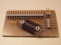
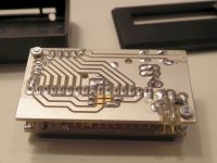
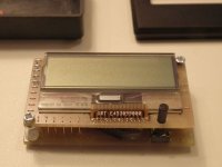
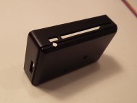
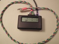
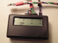
I have decided to build a heating case for testing my controller and it's individual parts at both elevated temperatures and lower temperatures. I have my Fluke and it's thermoprobe, but I need the Fluke to measure various voltages and currents while testing, so I just finished a small thermometer project I started to have something to measure the temperature with.

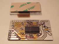
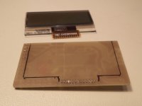
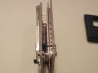
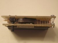
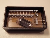
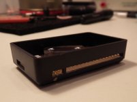
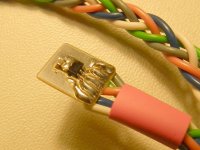
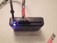
It basically consists of a PIC18F2620 driving a LCD screen from a Bang & Olufsen Beocom 6000 handset. It has connections for 6 SPI driven temperature sensors, in my case the ADT7301 from Analog Devices (-40°C to +150°C). The temperature sensors share VDD, VSS, SCLK (clock), DOUT (data out) and DIN (data in) pins. They each have a CS (chip select) pin. The connections are spread out on two 8-pin headers, each 8-pin connector can then have 3 sensors attached.
I can easily use other 3V sensors, like the TC77 from Microchip or even an analog output sensor like the MCP9700 from Microchip since 5 of the CS pins on the PIC are also analog inputs.
I also made a connector for the UART of the PIC so I can have the temperature output to a serial port on the PC at any interval for logging purposes.
Input voltage range is 3.5V to 13V, reverse polarity protected. Current consumption is 3-4mA with sensors connected, it could be lower if I would let the PIC go to sleep most of the time but that was not a priority right now.
There is a button for switching between current, maximum and minimum temperatures. A fun fact is that the black plastic pin for the button is made from a LEGO Technic axle, mounted to the tactile switch with the same VHB (very high bond) tape used to mount the LCD display 8)

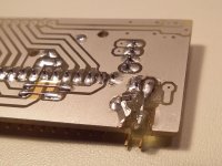
Final step is to make some more sensor boards with that thin 0.7mm PCB. The one in the pictures is a bit oversize so I could fit the wires I had in stock, that is some normal easy-to-melt-the-jack wire there, I have ordered some 190°C rated PTFE insulated 28AWG wire for the purpose.

Also, I need to find something to coat the sensor boards with, perhaps some high temp epoxy or something else that can handle up to 150°C.
 

Attachments

  • 01.jpg
    01.jpg
    50.1 KB · Views: 2,018
  • 03.jpg
    03.jpg
    64.2 KB · Views: 2,018
  • 04.jpg
    04.jpg
    73.6 KB · Views: 2,018
  • 05.jpg
    05.jpg
    35.3 KB · Views: 2,018
  • 06.jpg
    06.jpg
    58.1 KB · Views: 2,018
  • 07.jpg
    07.jpg
    44.5 KB · Views: 2,018
  • 08.jpg
    08.jpg
    36.9 KB · Views: 2,018
  • 09.jpg
    09.jpg
    31.1 KB · Views: 2,018
  • 10.jpg
    10.jpg
    27.3 KB · Views: 2,018
  • 11.jpg
    11.jpg
    64.3 KB · Views: 2,018
  • 12.jpg
    12.jpg
    33.9 KB · Views: 2,018
  • 14.jpg
    14.jpg
    58.2 KB · Views: 2,018
  • 15.jpg
    15.jpg
    55.6 KB · Views: 2,018
  • 16.jpg
    16.jpg
    60.3 KB · Views: 2,018
  • 17.jpg
    17.jpg
    33.6 KB · Views: 2,018
Project has been on standby for some time now. An exiting new job at Siemens Wind Power has been taking all my intellectual strength, and the season for RC model airplanes has begun so I have spent my time on work and my RC hobby.

One of my new colleagues are driving around in a Mini-El and we started talking about brushless drive systems for the little car: http://en.wikipedia.org/wiki/CityEl

That gave me a fresh boost of motivation for getting some more work done on the project.

I took out the box of components I ordered some months ago and found the need to order some more SMD storage boxes, the ones I use now is out of production and are really for paint, not electronics :lol:

I found some nice cheap boxes on ebay:
http://www.ebay.com/itm/150929048243
http://www.ebay.com/itm/141517653004

And then this caught my eye:
http://www.ebay.com/itm/261654504713

This new cheap WiFi module is perfect for my controller! The RN131 I already have is also good, but it is bigger and much more expensive, so I had to order 3 of those ESP8266 modules :D

While waiting for my orders from ebay, I have the components for making the gate driver boards for the ACPL-337J at hand, so enough with the posting and moving on to PCB design work 8)
 
Back
Top