JP spot-welder, FET-switched, timed adj. pulse

I was fortunate to receive one of the last welders before riba went on hiatus. And it seems that perhaps folks are having varying degrees of success with .3mm nickel, so thought I'd report my results as well.

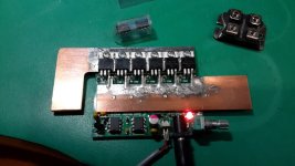
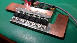
I have an 80 amp-hour group 24M deep cycle battery. Because I knew I wanted to go with .3mm nickel for at least my series connections, I went ahead and built the diode mod with a couple of IRFB7430PBF-ND from Digikey. I fully charged the battery, and gave things a whirl with various thicknesses of material with some dead C batteries. Everything up to .3 welds effortlessly and completely. Even at full power (longest pulse), however, my setup doesn't weld .3 reliably.

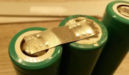
But that said, I was trying to weld a single piece of nickel with no slot i.e. both electrodes on the same solid strip of nickel. But per some of the posts I read here, I tried welding with the electrodes on two separate pieces so the current would have to go down and through the battery and voila, excellent welds. Removing the nickel requires pliers and results in complete perforation at the weld site. I'm going to experiment with creating strips with slots using a dremel to see how that compares.

At any rate, I can confirm that a single somewhat larger battery will suffice for welding .3mm if you can force the current down through the battery instead of shorting across the strip.
 
Alan B said:
A slot punch would be great, like a metal nibbler but making a tab slot shape instead. I wonder if something like that exists?

The slot would need to be pretty narrow. I can't think of a common tool to do that. A drill hole would help.

It might work to simply make a cut with sheet metal shears on the end of the strip. The sides of the cut would still touch each other, but I bet it would increase the resistance enough to get the desired effect.
 
Here is my completed operational but I still need to run balance wires and parallel connections, but I'm using it without those right now. It is a 20s14P, using 280 3500MAH cells.

I know some of you thought my pack may seem unsafe, but I believe it is extremely safe. I wrapped the pack tight with kapton tape so there should never be a loose wire. The wires are held firmly to the pack.

The pack is also inside my frame so tight I need to actually push it in and out with my knees. Pack is then compressed from the sides with foam when I put the side covers on.

The closed cell foam compresses around the cell edges, in a way molds around the pack to hold it in very firmly.

Series connections I used 7 separate 16 gauge copper wire, which is equivalent to about an 8 gauge wire. Think about it, you would need to connect each series group with four 8 gauge wires of nickel to get the same resistance. Voltage losses are extremely low.

Pack is perfectly cell balanced between all cells in the very oddly shaped pack which is not rectangular or square. I even used the 16 AWG wire to connect to my controller in equal length. I also needed the wires to be flat when coming out of the pack because frame width is only 76 mm.

It was a real pain to build it this way. 140 separate wires, 280 nickel tabs to be tinned. 280 wire ends to be tinned. 280 nickel plates to be cut and welded. Wires needed to be soldered to all the nickel. Difficult to align all the wires to be as short as possible and to not overlap another wire because the pack needed to be perfectly flat. All the nickel with wires attached had to be spot welded, which moved around especially when connected on one side. Took me hours to build it this way. Each series group probably averaged about 3 to 4 hours to do. Very detailed work to get it done without overlapping wires and wires the same length.

I would have loved to just weld some nickel if I thought it was better that way.


Cowardlyduck said:
Looks ok to me Offroader.
I like the fact that you can still see the cells through the kapton tape. Makes for easy visual identification if something goes wrong.

I also like how you've used every bit of available space in that frame. What kind of range are you expecting from the pack?

Cheers

Yes seeing though it is helpful. I actually have probed through it and tested individual cells.

The pack is rated at 3.5 KW, but the Sanyo 3500's are more like 3300 MAH cells, so its more like a 3.3 KW pack.

I hope to get about 2800 watt hours from my max-e, which would be about 72 KM of hard miles. Or hard riding at around 7.5KW of power. My old pack of 24 packs of 6s 5000 MAH, I only got about 48 KM on average in the summer or around 1800-2000 watt hours from my max-e.

I didn't get to test a full battery yet, hopefully in the next few days I'll test a full charge and see how much I can get out of it.
 
fechter said:
Alan B said:
A slot punch would be great, like a metal nibbler but making a tab slot shape instead. I wonder if something like that exists?

The slot would need to be pretty narrow. I can't think of a common tool to do that. A drill hole would help.

It might work to simply make a cut with sheet metal shears on the end of the strip. The sides of the cut would still touch each other, but I bet it would increase the resistance enough to get the desired effect.

I went ahead and tried a dremel first. 5 out of 6 welds were good and the bad one I credit to the inconsistent surface (I have been re-using this AA battery, just filing it as smooth as I can between tests). Pics....

First shows 6 welds onto a AA battery with a single piece of slotted 8mm wide x .3mm thick nickel:

IMG_1364.JPG

Next, although blurry, shows the perforations in the .3 nickel after prying the strip off with pliers:

FullSizeRender 2.jpg

This is the top of the battery, also after removing the strip:

FullSizeRender.jpg

Lastly, the standard dremel cutting disc I used to cut the slot... Came with the kit, I'm unsure of its thickness...

IMG_1367.JPG
 
Hi all, I need a spot welder to make my battery, JP is still busy ? :cry:
 
riba2233 said:
Hi, unfortunately I'm not busy but pretty sick. So, maybe you could see if someone close to you would be wiling to lend you or rent you one, or maybe even weld cells?

I live in France so it's hard to find someone close to me :(

Please send me PM later if you could sell one to me, I have maybe one or two month before my ebike is ready, I hope you get better soon :wink:
 
This is the first battery I built.
Dremel battery 3S Sony VTC5.
The old one:
20160311_213558_1.jpg

The new one:
20160411_235442_1.jpg
 
Just waiting on the open source info for this JP spot welder, did he post that info or is it scattered in with the battery config & weld posts?

Be nice if there's a seperate thread for that, rather then gunk up his spot welder thread.
 
Sorry to hear you are sick Riba! Hope all is ok man.
 
I'll share my spot welding results as well. I use 4x 90Ah LFP cells as power source. Lots of power. Already welded lots of nickel to cells with this thing. Everything works well! Mostly 0.15mm nickel and 18650 cells. Welds are clean and nickel tears around the weld if I try to pull the strip off. I tried welding resistor leg directly to a cell and it was a success. You can build Tesla-style cell fuses this way. Flatten the wire a bit and you can weld it easier to a cell end. We did a single 10S10P pack for a e-cycle using cell level fuses. 1/8W resistor leg takes a bit over 6A to burn. 1/4W leg tolerates more current than cells can handle :D But when 10P configuration is asked to deliver only 20A at most 6A fuse works if any cell goes bad. Used laptop cells you know.

Thank you Jakov. Sorry to hear about your illness. Let's hope everything turns out all right!
 

Attachments

  • 20160420_132900.jpg
    20160420_132900.jpg
    69.8 KB · Views: 1,183
I don't need a welder yet (i just like to have a read) great stuff!!, just chimed in to say "Get Well Soon"....
 
I wanted to say a big Thanks to Jakov for sending me the spare chip that i blown on my spot welder.

It is back to life ! and work like a charm!

I blown that chip because of stupid error while playing with it by shorting the probe together to see wiere dancing... :roll: but the probe was making a big loop around the two chip of the spot welder and probably that the large magnetic pulse zaped that chip...

As you can see i have maximized the drain and source conductivity to rail and used copper instead of aluminum. These copper bar was used in the Zero motorcycle battery capable of 700A continuous. I also soldered the mosfet to the bus. I have about 50x quality 47 000uF low ESR 35v capacitor that i will use as powerbank buffer.

Doc
 

Attachments

  • 20160420_233702 (Personnalisé).jpg
    20160420_233702 (Personnalisé).jpg
    91.6 KB · Views: 1,810
  • 20160420_233719 (Personnalisé).jpg
    20160420_233719 (Personnalisé).jpg
    119.7 KB · Views: 1,810
Good job doc.


Get well soon Riba
 
I am really curious to see how well it will perform with capacitor bank. I have few board that was made for laser hair removal device that was pulsating a 400W diode. Each bank is 10 parallel 47000uF 35V lo ESR. I have measured about 1.05 miliohm per bank... in the perfect world thats, about 12 000A at 12V but including the 6 fet rds on, and wiring i guess i could acheive about 3 miliohm total witch is about 4kA or less.. but maybe i forget some other loss to take in account ? rise time, inductance etc...

Doc
 
wow! that is a real work of art doc.
ill be keen to see the effects, and would possibly mod my own like this for higher current at some point if i can learn how.
RTL
 
Back
Top