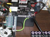
JP spot-welder, FET-switched, timed adj. pulse

fechter said:
Yes, these were exeptionally good at high rates. This is a sealed AGM type.

I wanted to install a diode so I don't need to worry about inductive spikes. I made one from a pair of FETs I had lying around. The gate and source are shorted so the FET is off, and we are using the intrinsic body diode. FDP8860 are only good for about 500A each. Later I found some IRFB7430 which have a body diode pulsed rating of 1,576A each! That should be enough. I could have bought some diodes, but I had FETs in stock and they might actually perform better than most diodes in this application.

I just took the FETs and snipped off the middle (drain) leg. The remaining legs just get soldered together. Pretty much all FETs in this package have the same pin out.

Diode Assembly:

View attachment 1

Connection detail:


Does the FET neet to turn on to conduct with configured like that? sorry I am not familiar with this use.
I wonder if it might have some delay compared to a normal Schottky diode. You need the diode to conduct as quickly as possible to help.

I guess it should be pretty fast. I understand how it works now :)
Turn on should be typical for a MOSFET, pretty fast... enough to help at least :)
 
The datasheet indicates the turn-on time is so fast it's hard to measure. Picoseconds. We don't really care about turn-off time, but it's pretty fast too.
 
So which is better?

This:
SOT_227_4_DSL.jpg


Or this:
file.php


Or will both solutions give the same result? Because I'm poor and prefer the cheaper MOSFET option.
 
mistercrash said:
So which is better?

This:
SOT_227_4_DSL.jpg


Or this:
file.php


Or will both solutions give the same result? Because I'm poor and prefer the cheaper MOSFET option.

I think the MOSFET solution will work just fine.
You can also use a bunch of cheaper diodes in parallel too.
 
For the occasional hobby user, Spot Welding .2mm Nickel strips using a 800CA AGM Spiral Wound Optima Red Top battery, will this add-on be helpful? If the answer is yes, I am going to install it just to be safe.

Are these the FETs you suggest?

http://www.digikey.com/product-detail/en/IRFB7430PBF/IRFB7430PBF-ND/3454578

I read back a few pages and see that this isn't really required in my situation. Is it easier on the electronics if I install it anyway?

fechter said:
Yes, these were exeptionally good at high rates. This is a sealed AGM type.

I wanted to install a diode so I don't need to worry about inductive spikes. I made one from a pair of FETs I had lying around. The gate and source are shorted so the FET is off, and we are using the intrinsic body diode. FDP8860 are only good for about 500A each. Later I found some IRFB7430 which have a body diode pulsed rating of 1,576A each! That should be enough. I could have bought some diodes, but I had FETs in stock and they might actually perform better than most diodes in this application.

I just took the FETs and snipped off the middle (drain) leg. The remaining legs just get soldered together. Pretty much all FETs in this package have the same pin out.

Diode Assembly:

View attachment 1

Connection detail:

 
Yes, those FETs should work fine. It's cheap insurance. With the diode, it should be pretty bullet-proof.

Here's the diode installed on my little battery:

Diode Installed.jpg


Just for fun, I made about a 2cm coil from some scrap 12ga wire and pulsed it. It was about 6 turns. The coil really jumps when you fire it. I placed a bolt next to the coil and it got sucked in, but not very fast. I'm petty sure this would blow up the FETs without the diode. The coil got pretty hot, but the diode didn't get warm. I think the pulses going through the diode are very short duration.
 
Can someone explain what this Diode is exactly doing? Current flows from positive to negative, so why is the diode allowing current to only from the negative side to the positive side?

How can electricity ever flow from the negative to the positive through this diode?

I am discussing this of course from the conventional current flow.
 
Offroader said:
Can someone explain what this Diode is exactly doing? Current flows from positive to negative, so why is the diode allowing current to only from the negative side to the positive side?

How can electricity ever flow from the negative to the positive through this diode?

I am discussing this of course from the conventional current flow.

It gives the current a path to continue flowing through the leads when the welder FET's turn off.

Otherwise, the current is forced through the fets at the avalanche voltage. The FETs are designed for alot of avalanche current, but just not 600A worth each.
 
If there was no inductance, the diode wouldn't do anything. All wires have some inductance. Making a coil causes even more inductance. Energy gets stored in the magnetic field while current flows in the wire. Suddenly stopping the current causes the magnetic field to collapse as it tries to maintain the current flow. This creates a big voltage spike across the FETs and can blow them. The diode circulates this spike back into the battery, limiting the voltage the FETs see.
 
Thanks, I got it now :D . I'm going to hook up my diode and try and attempt .3 nickel welding over the weekend.
 
fechter said:
If there was no inductance, the diode wouldn't do anything. A wires have some inductance. Making a coil causes even more inductance. Energy gets stored in the magnetic field while current flows in the wire. Suddenly stopping the current causes the magnetic field to collapse as it tries to maintain the current flow. This creates a big voltage spike across the FETs and can blow them. The diode circulates this spike back into the battery, limiting the voltage the FETs see.

Correction... it doesn't flow the current "back into the battery," it simply gives the current a path that bypasses the FET's. The current continues to flow in a loop made by the welding leads and the diode circuit, a few microseconds.
also, the voltage spikes to about 28V at the MOSFET's. This doesn't change with the diode added. This is because the MOSFETs act like a diode with a voltage drop at ~28V when they are turned off.
It's a question of the amount of current and duration of that current at 28V.
With no diode, the full current has to flow, so if you're welding at 3,000 amps, the MOSFET's will see 3,000 amps at 28V = 84kW for a microsecond or so.
 
okashira, I know you commented on this before but why can I use 10 gauge wire to connect the mosofet? Wouldn't it have to be thick like the probe wires to work effectively?

Will using thicker wire than 10 gauge give my fets more protection?

Thanks, It is that 10 gauge wire would be easy to use for me, but I don't want to limit the fet protection of the diode by going small, when all the other wires used are thick.

Should I like run two 10 gauge wires to the diode?

Thanks,
 
Offroader said:
okashira, I know you commented on this before but why can I use 10 gauge wire to connect the mosofet? Wouldn't it have to be thick like the probe wires to work effectively?

Will using thicker wire than 10 gauge give my fets more protection?

Thanks, It is that 10 gauge wire would be easy to use for me, but I don't want to limit the fet protection of the diode by going small, when all the other wires used are thick.

Should I like run two 10 gauge wires to the diode?

Thanks,

The current flowing through the welding leads is milliseconds
The current flowing through the diode is in microseconds
10awg would be fine
 
okashira said:
Correction... it doesn't flow the current "back into the battery," it simply gives the current a path that bypasses the FET's. The current continues to flow in a loop made by the welding leads and the diode circuit, a few microseconds.

Yes, quite right. I was thinking of a different topology.

Using the battery negative as a reference, as soon as the voltage on the drains goes above the battery voltage (plus the forward drop of the diode), the diode will start conducting. This will clamp the voltage to a value hopefully below the point where the FETs start avalanching, won't it?
 
I checked source drain voltage with diode in place and it definitely still avalanches for a few microseconds.
Ill scope it up again when I get time, also record diode current, pulse current, avalanche current at the same time on different channels
 
100_0534.jpg

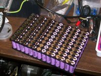
Coming along. This is going to be a 14s,9p pack.

One thing I ran into with my tiny battery is after a few hundred welds, I started to lose weld power. After checking things out, I determined that I had simply drained the battery faster than it was being recharged. For a decent firing rate, it takes about 3A of charge current to keep up.
 
I have one of these jump starter batteries.

http://www.amazon.com/Jump-N-Carry-JNC660-1700-12-Volt-Starter/dp/B000JFJLP6/ref=pd_sbs_263_1?ie=UTF8&dpID=51eXCN9XAyL&dpSrc=sims&preST=_AC_UL160_SR158%2C160_&refRID=1KC7Z5SRP2PSP6TV4DGG

Specs are:

1700 Peak amps
425 Cranking amps.

If I clamped this on to my 800 cranking amp battery in parallel does anyone see any issues?
I will be using a diode between the positive and negative.

What worries me is this is rated at 1700 peak amps, seems that jump starters may put out a lot of power very quickly.

Would this be like adding 1700 to my already 800 car battery to give me a total of 2500 cranking amps? Or should I assume it will only output 425 cranking amps as rated? This peak amps is throwing me off here because I can't find much information about it, and only jump starters use this value.

Thanks
 
Those batteries are overrated, I wouldn't use those.

Battery can most usually put double the rated CCA amps when used with welder.

I mean you can try, but I really can't tell you what to expect, maybe it will be weak, but maybe it will be too strong... It's hard to tell.
 
Again, why dont you just go out and buy a $20 truck battery from your local automobile junk yard?

For $130 you are spending on that battery jump starter, you could buy 2 or 3 twenty dollar truck batteries. Those specs on that are probably way way exaggerated.

Every junk yard battery I have ever bought was good!! reputable junk yards wouldn't sell dead or dying batteries, because the employee will just hook the battery up to a battery tester, takes them no time at all. I usually just go for the cleanest battery that is a brand name, not some Wal-crap-mart no-name product.

In your case I would look for the biggest battery you can. In my city of 1M citizens we have a dozen junk yards, Pick-N-Pull has 2 locations here, they are a nationwide chain and the place I always go to because they have the biggest lots.
 
Sorry guys I think you misunderstood. I own that already, well my father owns it but doesn't use it much so I can connect that to my 800 cranking amp battery for extra power in parallel.

Here is the battery I own, but I want to weld .3 nickel and this battery alone doesn't seem strong enough by itself. I can quickly just clamp that onto my existing battery terminals for a boost in power.

Problem is I will be adding 800+475 cranking amps, but that jump starter has a high peak amp rating. I will be using the diode which supposedly should allow me up to 2000 cranking amps.

I am worried about it being too many cranking amps for the welder and blowing the fets.

 
Offroader said:
Sorry guys I think you misunderstood. I own that already, well my father owns it but doesn't use it much so I can connect that to my 800 cranking amp battery for extra power in parallel.

Here is the battery I own, but I want to weld .3 nickel and this battery alone doesn't seem strong enough by itself. I can quickly just clamp that onto my existing battery terminals for a boost in power.

Problem is I will be adding 800+475 cranking amps, but that jump starter has a high peak amp rating. I will be using the diode which supposedly should allow me up to 2000 cranking amps.

I am worried about it being too many cranking amps for the welder and blowing the fets.


Batteries don't have "amps"
dont be confused or mislead by "cranking amps," rating as it has little bearing on how many amps you'll be pulling when you weld.
I can add that the diode has completely stopped my mosfet problem. I've had this welder last at least 5x longer then past welders and still have not blown a single mosfet since I installed the diode.
I've been welding very aggressively too. often keeping it at full power and charing to 8.4V, which I shied away from in the past.

My problem now is my welding leads get insanely hot - I have to dunk them in a big cup of ice water, but the mosfets are barely warm!
 
okashira said:
I've been welding very aggressively too. often keeping it at full power and charing to 8.4V, which I shied away from in the past.

My problem now is my welding leads get insanely hot - I have to dunk them in a big cup of ice water, but the mosfets are barely warm!

You sir, are crazy! I am about to add the FETS that Fechter showed. Mostly because they are a lot cheaper. Do you see any issues with this vs the diode design you are using?
 
Back
Top