HAL9000v2.0
10 kW
Miles said:Hi Hal.
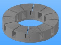
It would mean substantially more machining. This way, you just need to trim the edges with a cut-off saw. If you want anything other than a parallel inner core, I think you might as well machine the whole thing from a laminated blank.
I don't get this. your core plates are all different so why it would ask more machinning? Just make this inner part of a "H" on every next part a little wider. That leads us to next question: Whay would you like parallel inner core? When you add area thet you get extra inside isn't this better then the parralell? Must draw this...to many parameters... I think I can't explain it with words...
")