New "TSDZ2 Torque Sensor Central Motor"

casainho said:
Testing TSDZ2 and LCD3 flexible OpenSource firmwares

So, just before the day that I would ride 75km on the mountain, where everyone says it is a tough ride, I did "burn" my TSDZ2 motor as I did explain here. Knowing that we would go to a very high point of the mountain and would be really bad if something would fail on my ebike, I though if I should trust on the flexible OpenSource firmwares of my own development. I really wanted to use the advanced features of this firmwares because I needed to optimize the battery range.... and so I did!!


The ride was perfect, TSDZ2 always working smoothly and strong. It took me about 6 hours and I took with me 2 batteries, in total of 900 watts/hours and I used 650 watts/hour. Most of time I limited on LCD3 the power to be 250W or even at 150W, because a bigger value was hard to drive on the very narrow paths and also I wanted to go in group with the other riders without electric bicycles. Using that low power was great because I got a very good battery range and also TSDZ2 did not get hot. But I also took advantage of the max power possible from the motor, and sometimes I used the max power and I was able to climb the very sharp paths were other professionals could not.

So to resume: I do trust well on TSDZ2 and LCD3 flexible OpenSource firmwares and the advanced features were very important for this long and hard ride, where I had to optimize battery range as also I prefer a constant electric power assist unlike with original firmware that gives variable power.

Very good!

Because of holidays I think I will install these nice features in October.

Power defenition I hope is a very good tool.

Keep going.

Thanks
 
feketehegyi said:
So, my plan for the bluetooth module is to have these parts:

It's written that the HC05 module works on 3.3v TTL. But the Motor controller works on 5v TTL, so the level shifter is needed. Also a 5v and a 3.3v power source is needed therefore I plan to buy such 2 regulators.
They cost together approximately 5EUR or 5.8USD. Then a switch max 1EUR, and a poor man's cable connector for 0EUR.
For this latter I assume can the extension cable used as well: https://www.eco-ebike.com/collectio...oducts/extension-cable-for-tsdz2-speed-sensor We'd only need the male part of this. Unfortunately this kind of cable connector is rarity.
Then pack all those things together and attach to the frame and plug into the LCD cable connector - and use my android app as LCD display via bluetooth. So, this's my next plan to try out.
For those of us still using the VLDC5 display , which has a USB port.. (Reported to be a 5v Phone charger only ??) ...is it possible we could simply use a suitable USB Bluetooth "dongle" and fix some jumper links from the display board to pick up the RX & TX connections to the USB port ?
This would avoid the 5v and 3.3v requirements , and retain the original controls (on off etc),
Probably totally impossible ????
 
Hillhater said:
For those of us still using the VLDC5 display , which has a USB port.. (Reported to be a 5v Phone charger only ??) ...is it possible we could simply use a suitable USB Bluetooth "dongle" and fix some jumper links from the display board to pick up the RX & TX connections to the USB port ?
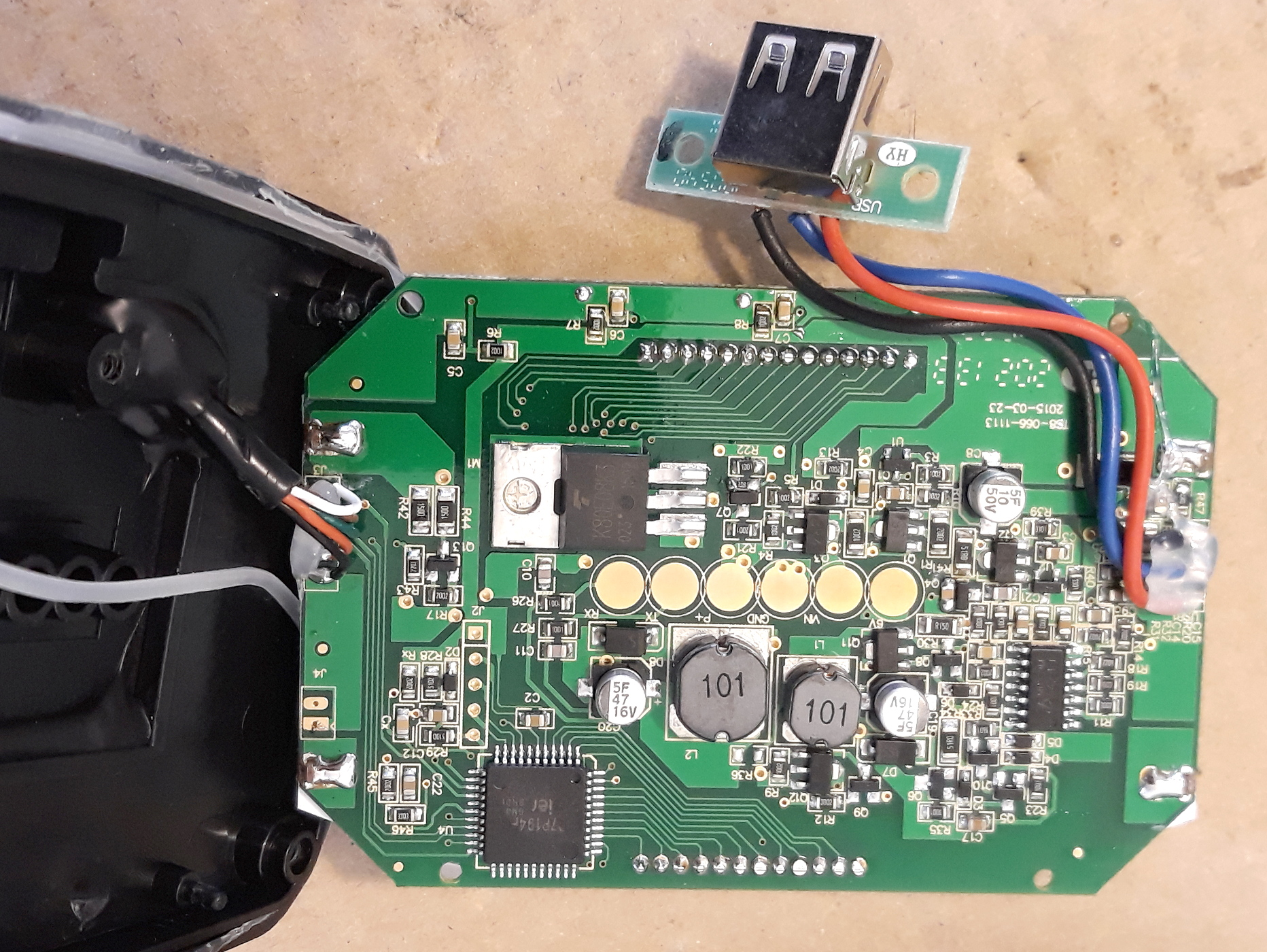
You shoild read my notes about that display, I have pictures of the inside, etc.
 
casainho said:
Hillhater said:
For those of us still using the VLDC5 display , which has a USB port.. (Reported to be a 5v Phone charger only ??) ...is it possible we could simply use a suitable USB Bluetooth "dongle" and fix some jumper links from the display board to pick up the RX & TX connections to the USB port ?
You shoild read my notes about that display, I have pictures of the inside, etc.
Thanks C'....are they in this thread somewhere ?
 
Hillhater said:
For those of us still using the VLDC5 display , which has a USB port.. (Reported to be a 5v Phone charger only ??) ...is it possible we could simply use a suitable USB Bluetooth "dongle" and fix some jumper links from the display board to pick up the RX & TX connections to the USB port ?
This would avoid the 5v and 3.3v requirements , and retain the original controls (on off etc),
Probably totally impossible ????
There's bidirectional communication between Motor and LCD. If you would like to have both, then the DIY display should be passive only. Just to show the values, not to send anything to Motor as that would interfere with stock LCD sendings.
For RX, TX you either need a HC05 or similar module to convert to Bluetooth, or a usb to serial converter if it is wired.
 
Hillhater said:
ThreeOnBoard said:
Hi all,
I have had the TSDZ2 for nearly two years (maybe 5000kms) on my Kona Fire Mountain with no issues. Recently as I began from a stop I heard a snapping sound and now the crank turns quite easily and the TSDZ2's gears don't engage. It appears that the electric motor is still working but it's not turning something it should. I inspected the gears and found no obvious issues. The blue gear looked fine. I removed the casing from the other side and couldn't see any obvious issues.

Does anyone have a suggestion as to what has happened or how to troubleshoot it? Could it be something within the internal motor? Could it be a bearing?

Thanks in advance,
Grant
Hi Grant,..Welcome to the "'sphere " !!
You need to understand that inside the "blue gear" is a roller sprag bearing (one way clutch).
The plastic outer gear may be perfect, but its possible for the inner clutch to have failed preventing the motor drive reaching the crank gears.
So , yes its possible that replacing the complete blue gear assy will solve your problem
https://youtu.be/CTbDKN2GzNE
[youtube]CTbDKN2GzNE[/youtube]


Excellent, I wasn't sure as I could only find reference to the blue gear teeth being affected. I will replace the blue gear and go from there.

Thanks,
Grant
 
Probably because you are the first person that got enough miles out of one of those blue gears to actually have the metal part fail :) I think Casainho only got 5 miles out of his blue gear!
 
Grant,..
sorry , i intended to add, you could try just stripping and cleaning that internal roller clutch whilst you are waiting for a new gear to arrive.
It may just be gummed up and sticky with all the use you have on it !
Good luck.
EDIT : ..there is also the possibility that the stub shaft with the pinion gear, that the blue gear fits on, is worn on the clutch surface, again resulting in lack of drive. You might want to replace that also just in case ?
 
casainho said:
Hillhater said:
For those of us still using the VLDC5 display , which has a USB port.. (Reported to be a 5v Phone charger only ??) ...is it possible we could simply use a suitable USB Bluetooth "dongle" and fix some jumper links from the display board to pick up the RX & TX connections to the USB port ?
You shoild read my notes about that display, I have pictures of the inside, etc.
Casainho,..Thanks for the tip, and the photos etc..
.. did you figure out the pin out links to the USB port ?...i could not find them.
Does any of those details change with the 8 wire connector cable on recent drives ?
Black ..Ground ?
Blue ...?.. 5v ? maybe
Orange... ? Rx maybe ??
4-1.png
 
So cool! Glad to hear about your adventures and experience. I too have loaded your open source firmware and updated LCD3 onto my bike and love the features - I did ruin my blue gear though - most likely not down shifting before I stopped (I was a bit sleepy this morning).

I am wanting to plug in my accessories with the split port, but don't seem to be able to read a voltage (usual 6v with the old display/firmware). Have you configured the backlight to also turn on the accessory lights with your open source firmware, or I have I made a mistake in wiring somehow?
 
pawepie said:
So cool! Glad to hear about your adventures and experience. I too have loaded your open source firmware and updated LCD3 onto my bike and love the features - I did ruin my blue gear though - most likely not down shifting before I stopped (I was a bit sleepy this morning).

I am wanting to plug in my accessories with the split port, but don't seem to be able to read a voltage (usual 6v with the old display/firmware). Have you configured the backlight to also turn on the accessory lights with your open source firmware, or I have I made a mistake in wiring somehow?
Thanks!! And please give feedback after using it, if you found issues or have new ideas.

I think I didn't implemented lights control on motor controller, mainly because I don't use them. Ok, I will give a look at it later.
 
Hillhater said:
Grant,..
sorry , i intended to add, you could try just stripping and cleaning that internal roller clutch whilst you are waiting for a new gear to arrive.
It may just be gummed up and sticky with all the use you have on it !
Good luck.
EDIT : ..there is also the possibility that the stub shaft with the pinion gear, that the blue gear fits on, is worn on the clutch surface, again resulting in lack of drive. You might want to replace that also just in case ?
A previous poster reported a broken main motor shaft. That would correspond with a clunk and then no further power delivered.
 
Casainho
If we could get a temperature sensor in the motor and the board could read it then...

A friend of mine had the idea to use a PID feedback loop based on temperature to adjust AMPS up and down giving the max possible power

PID algorithms should be easy to find. If not try Betaflight which is used on drones and is also opensource.

The main loop could be PID

The power assist levels could run over the top to cut back the max power/amps based which assist level you are using, where level 5 is unlimited and runs at max power to maintain a safe operating temperature around 60 degrees ?

link to random arduino temp sensor
https://www.aliexpress.com/item/Fre...bvkXbOQpIxiByD-t9hoCLa4QAvD_BwE&gclsrc=aw.ds
or this one.
https://www.sparkfun.com/products/10988?_ga=2.73781585.2114195124.1533031684-500511168.1533031684
 
jbalat said:
Casainho
If we could get a temperature sensor in the motor and the board could read it then...

A friend of mine had the idea to use a PID feedback loop based on temperature to adjust AMPS up and down giving the max possible power

PID algorithms should be easy to find. If not try Betaflight which is used on drones and is also opensource.

The main loop could be PID

The power assist levels could run over the top to cut back the max power/amps based which assist level you are using, where level 5 is unlimited and runs at max power to maintain a safe operating temperature around 60 degrees ?
Thanks!!
Were you able to flash and use the flexible OpenSource firmwares??

Since I remember, the board has an header for connecting other wires (near where brake and throttle wires are connected). I really think we will be able to connect there a pin for a analog voltage/sensor.

I think that the most important part of this project (at least for me that I am not am hardware guy) is to find a sensor that can read well the temperature, is easy to source/buy online and is easy and quick to install <-- I think it really must be easy to buy and install, other way will be hard for the users to install and use this feature. Also, this feature should be optional, the system should work perfectly without this hardware!

No problem about PID, I already implemented PI controller for KT motor controller OpenSource firmware and in fact, I just copy that code to TSDZ2 project firmware, you can see the code here being ready to use: https://github.com/OpenSource-EBike-firmware/TongSheng_TSDZ2_motor_controller_firmware/blob/master/utils.c

And yes, we should limit the battery current (or maybe even motor phase current??) because it is the only source for heating the motor coils.
And yes, since it is a protection feature, it should have priority over current algorithm for motor power control. This will be easy to implement.

I wish other could help find the sensor, once we choose and decide by one, it will be hard to change for other one as it will take time to develop and test the hardware, firmware and the final result on the motor temperature (we will need to log over the time the temperature, currents, etc, to validate the implementation).
 
casainho said:
I wish other could help find the sensor, once we choose and decide by one, it will be hard to change for other one as it will take time to develop and test the hardware, firmware and the final result on the motor temperature (we will need to log over the time the temperature, currents, etc, to validate the implementation).

The DS18B20 is a cheap reliable temp sensor.

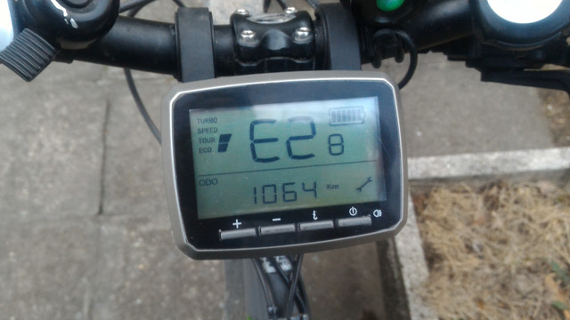
I think there are some kind of temp sensing built in the controller because when I used my bike in the winter under -10C an error show up in the display.

P_20180226_073517.jpg
 
casainho said:
I really think we will be able to connect there a pin for a analog voltage/sensor.

Have you ever tried to read in the ADC-Values from all AD-Channels? Perhaps there is an temp sensor on the PCB already. PCB is not the motor winding, but would work also maybe...

The implementaion for a KTY84 sensor is already working in the KT-open firmware, as you know. We only need to identify a free AD-pin and have to know, if it has an pull up resistor already.

regards
stancecoke
 
wheex said:
I think there are some kind of temp sensing built in the controller because when I used my bike in the winter under -10C an error show up in the display.
I verified again the board, I can't see any temperature sensor. Also I verified now that all ADC pins, now I don't think there is one free ADC pin. But even if there is a sensor on the board, I want to use another that is glued directly on the motor, so there is the smallest delay possible for reading motor temperature.

While I would prefer to use LM35 that has an analog output and would be like connecting a throttle, the true is that there aren't any ADC pins on the free header on the board. There are only 3 pins free on a header for PG0, PG1 and PC7 and those are only digital pins and with low pass filters on the board, they should work well for on/off sensors like brake.
So, maybe the best option we have is to use DS18B20 that has digital communication by 1 wire only (needs that user also solder a pull up resistor).
 
stancecoke said:
casainho said:
I really think we will be able to connect there a pin for a analog voltage/sensor.

Have you ever tried to read in the ADC-Values from all AD-Channels? Perhaps there is an temp sensor on the PCB already.
Yes, thanks for the idea. Also I have with me a board where I can see all paths to the SMT8 and ics...
 
And on Ebay we can find for less than $1 the DS18B20 with this good enclosure, that should be very good to glue to the motor:
s-l1600.jpg
 
And here OpenSource firmware for STM8 read DS18B20: https://github.com/eddyem/STM8_samples/blob/master/1-wire/onewire.c
 
Guys, some help /advice please..
First try at using the ST link to read the settings.
All set and connected as instructions, software installed..and configured .. (drivers for W7?)
Programmer opens and loads ok, but when i try to read data i just get a message..
"Cannot communicate with the tool
Wrong tool selection or check tool power supply or check previous session is closed "
..all connctions seem good, so
Is this a Driver problem ? ..
Or "tool selection" issue ?
 
Hillhater said:
Guys, some help /advice please..
First try at using the ST link to read the settings.
All set and connected as instructions, software installed..and configured .. (drivers for W7?)
Programmer opens and loads ok, but when i try to read data i just get a message..
"Cannot communicate with the tool
Wrong tool selection or check tool power supply or check previous session is closed "
..all connctions seem good, so
Is this a Driver problem ? ..
Or "tool selection" issue ?

Did you configure as shown in the pic attached?

I see you say "(drivers for W7?)"... just to be sure - you are running Win 7,8, or 10? Go to this folder:

https://drive.google.com/drive/folders/1u47wV3-g4PeRCuZhMP8_UhKqbDtBY0-9

download ALL, and then run: stlink_winusb_install.bat to install the driver properly.
 
casainho said:
And here OpenSource firmware for STM8 read DS18B20: https://github.com/eddyem/STM8_samples/blob/master/1-wire/onewire.c

Wow you have made some real progress on this !

I havent installed the opensource firmware yet on the motor but I have flashed the LCD3. I am worried about how to connect the new Display. I am cringing thinking of cutting the VLCD5 cable :shock:
 
eyebyesickle said:
Did you configure as shown in the pic attached?

I see you say "(drivers for W7?)"... just to be sure - you are running Win 7,8, or 10? Go to this folder:

https://drive.google.com/drive/folders/1u47wV3-g4PeRCuZhMP8_UhKqbDtBY0-9

download ALL, and then run: stlink_winusb_install.bat to install the driver properly.
Thanks ebskle,
Yes config using your guide as displayed .
Running Win 10,pro and downloaded/installed those files....just unsure how to check they installed correctly
..hence the ??
May have to try the ultimate ...... Switch off, and start up again !! :lol:
 
casainho said:
And here OpenSource firmware for STM8 read DS18B20: https://github.com/eddyem/STM8_samples/blob/master/1-wire/onewire.c

STM8 chip also offers free internal temperature sensor,
already in the same enclosure as the motor. Not saying
as accurate or fast as direct contact...

https://www.st.com/content/ccc/resource/technical/document/application_note/46/07/39/dd/1d/f8/46/7a/DM00028336.pdf/files/DM00028336.pdf/jcr:content/translations/en.DM00028336.pdf
 
Back
Top