
safeaschuck
100 µW
- Joined
- Apr 21, 2020
- Messages
- 7
Hi,
I have improved axle play, now I realised from a video on here recently that someone has used feeler gauges already but this is not as great in the torque sensor/axle through hole.
The hardness of the materials means they may bind together. As some said it is better than nothing.
Different people may have different problems. I suspect that the parts are all different sizes, this is what happens when things are made to a price level not a quality standard. Some do not wobble at all probably. I do not think it makes any difference if you buy from Europe, America or China. Same factory, same machine, same operator. Maybe there are special arrangements. I think probably not. Anyway, we have very, very cheap ebikes that may be 1/10th the price of a powerful purpose built machine so we improvise.
Here are my issues with moving pedals.
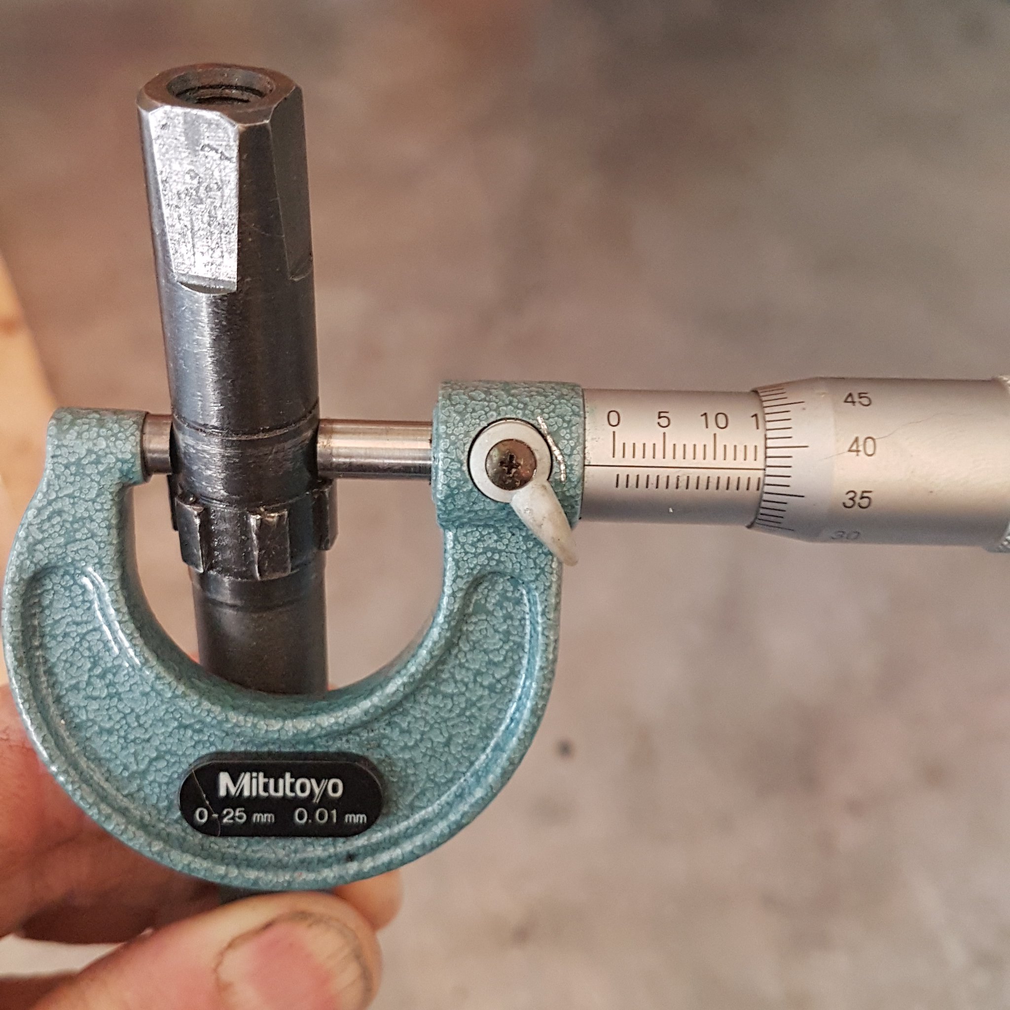
Micrometer measurement, Non drive side - 14.88mm, 0.12mm undersize. This is why the ball bearing is loose on the shaft.
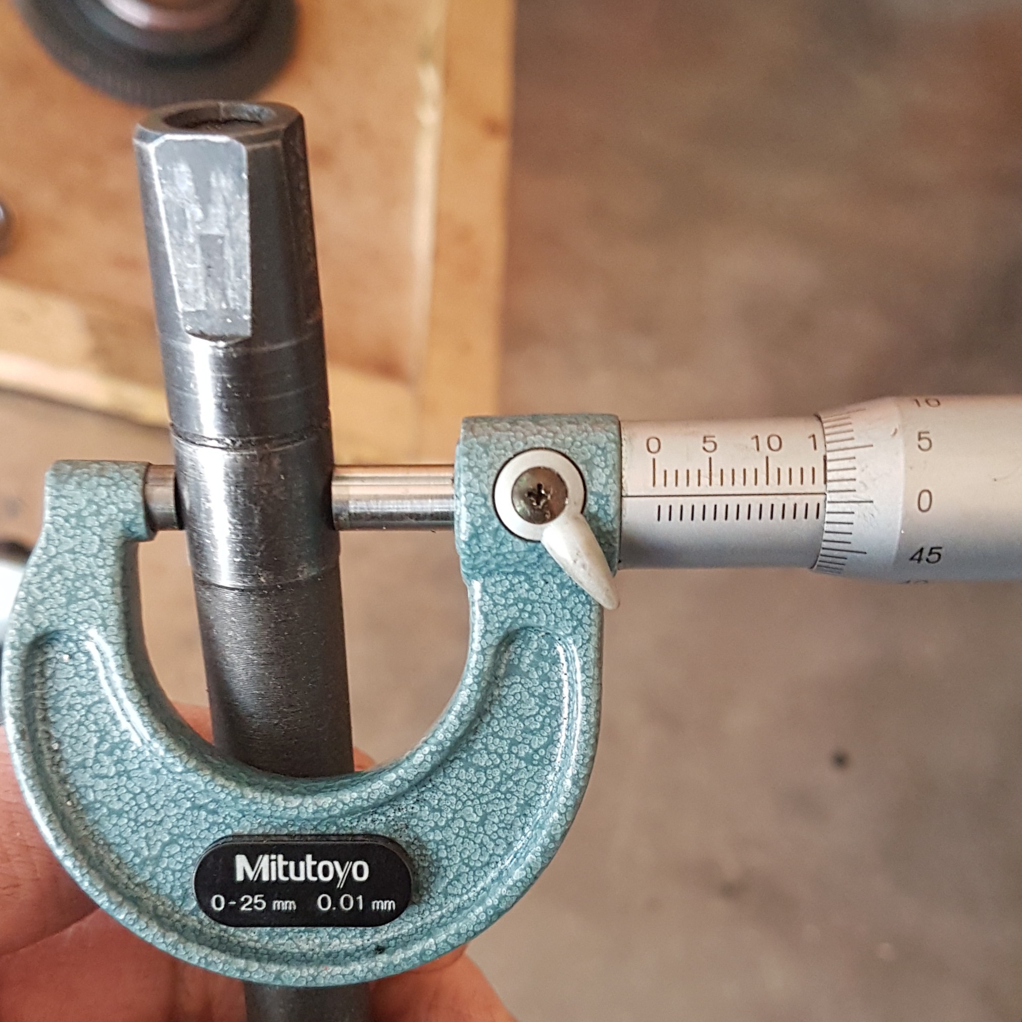
Measurement on drive side is actually VERY close to 15mm meaning Torque sensor hole is likely oversize.
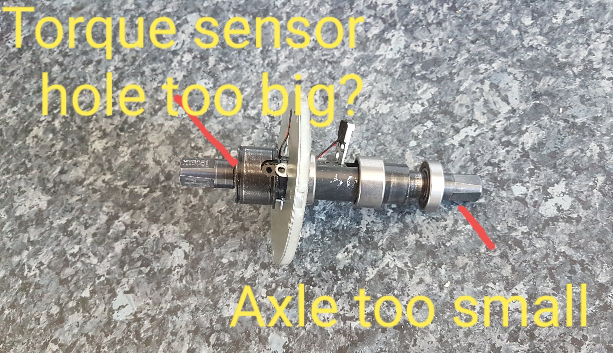
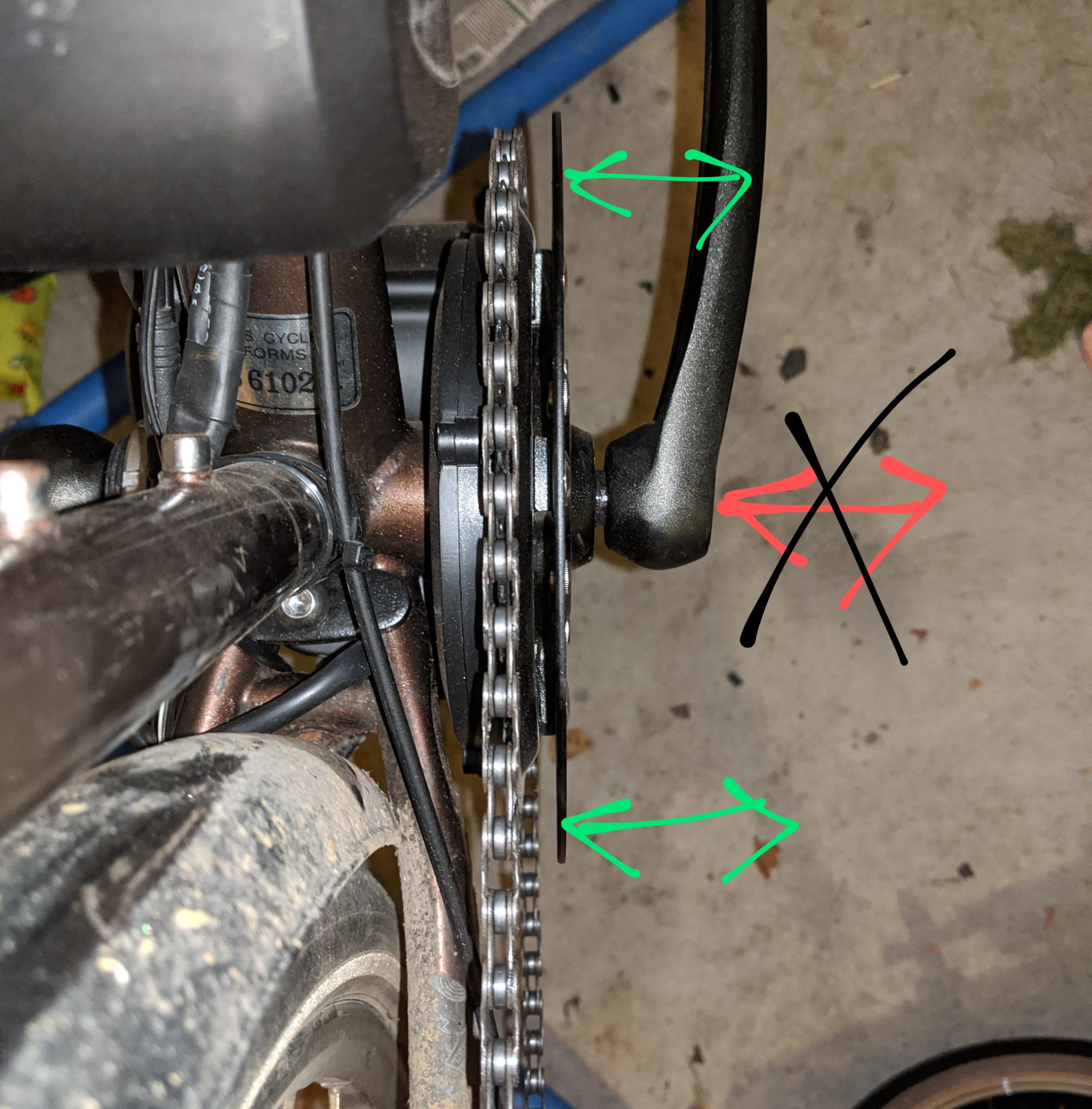
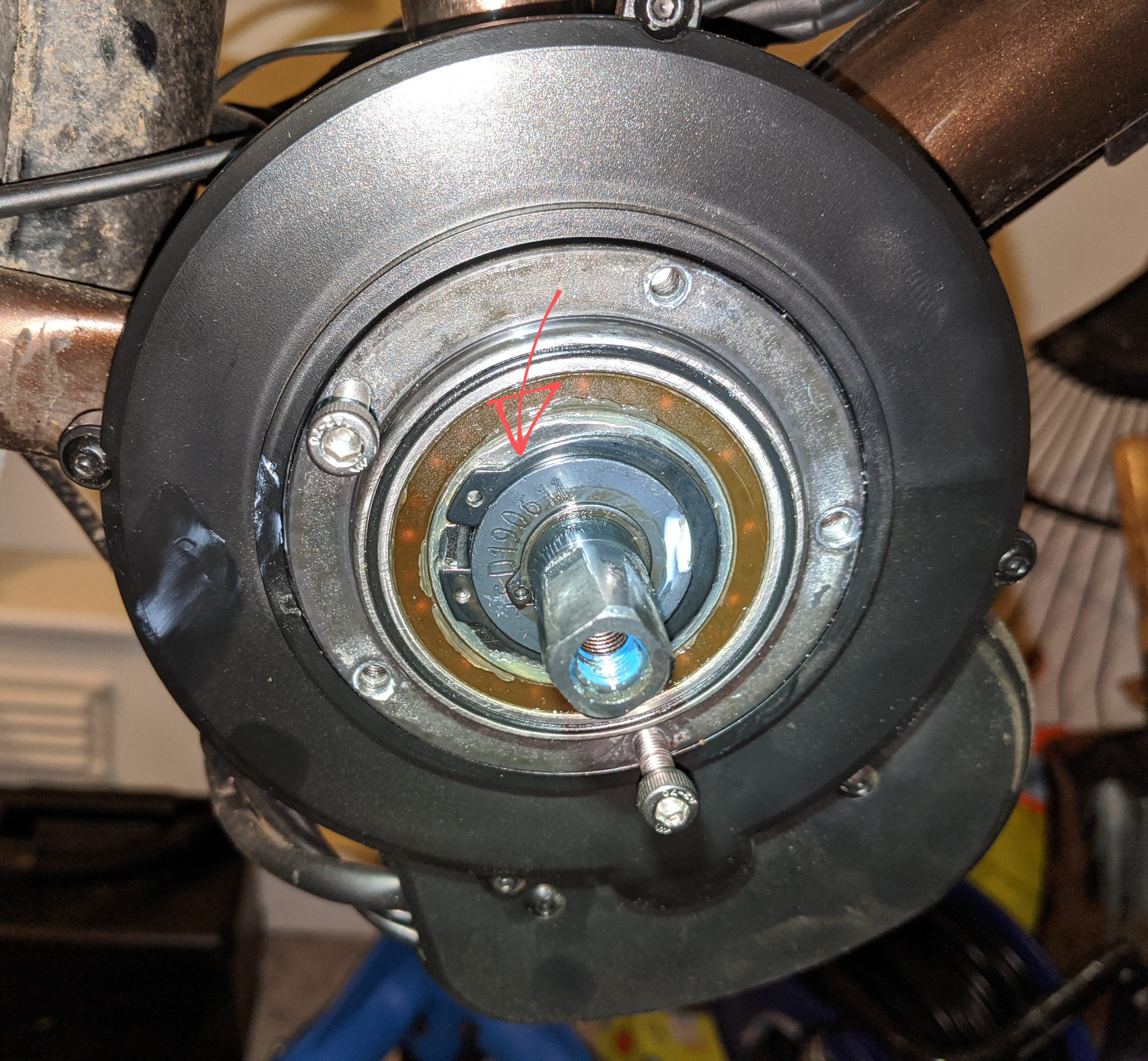
Picture showing why the axle wobbles. this is why my pedals feel like they are moving left to right instead of only round and round.
Here is my proposal, it has not been tested over a long period of time on this application. hopefully it will work O.K.
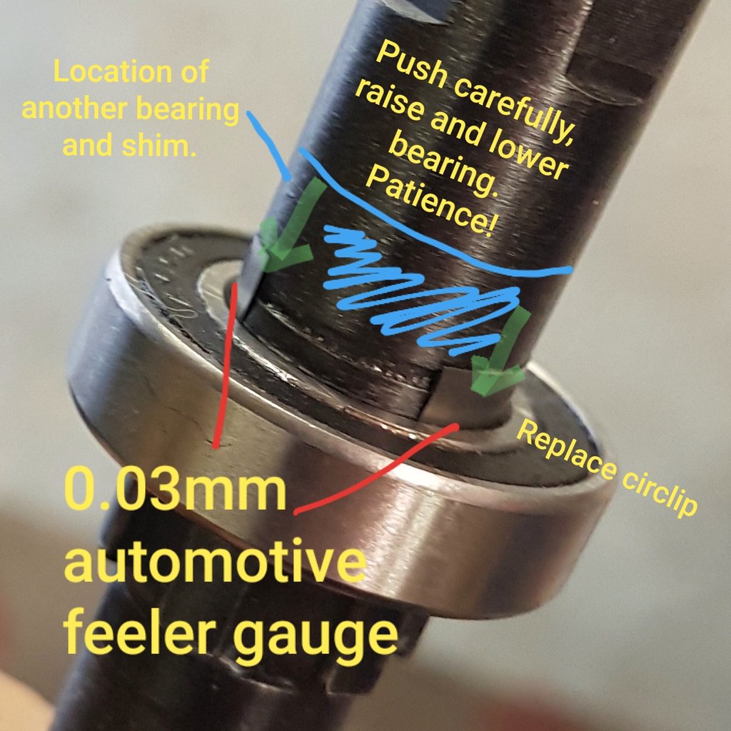
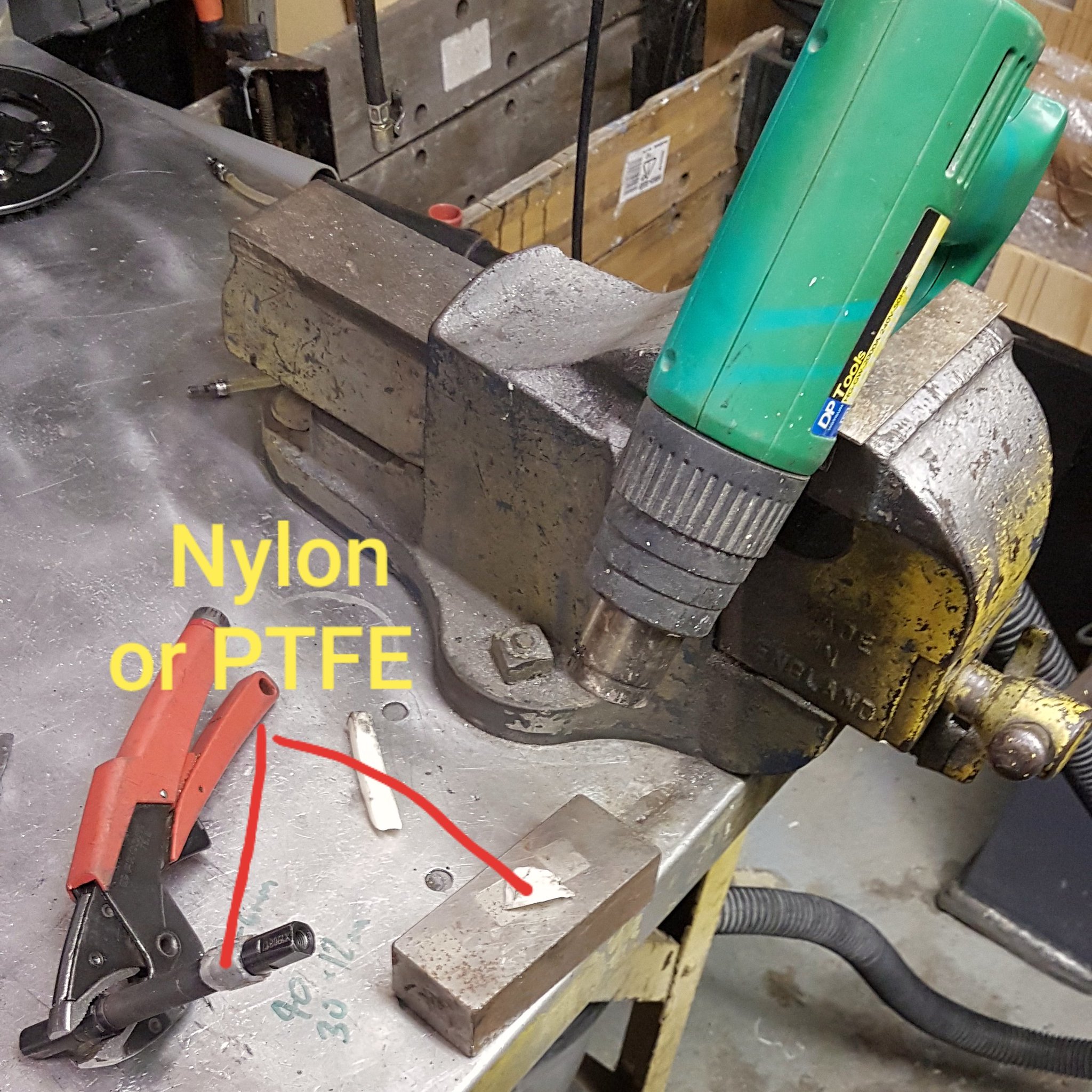
Non-Drive side, Feeler gauges:
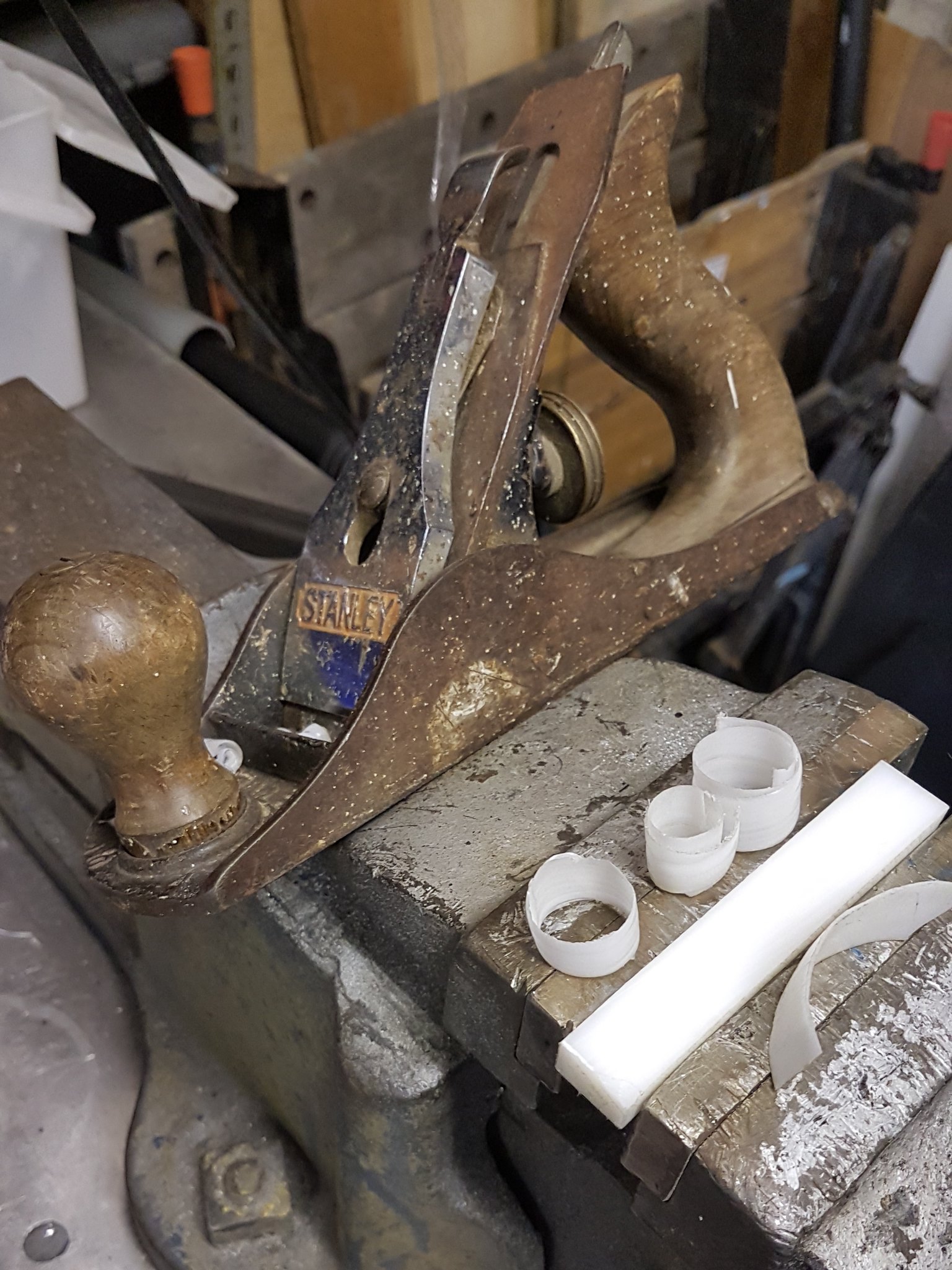
Drive side, Nylon or PTFE Wafer + Heat gun + sandpaper:
I had to have several attempts to properly attach the nylon here, it is tricky and although it stuck very well in the end, this may not last forever. This picture shows an early attempt, in the end I refined the system by making wafers of nylon with a hand plane, heated them with a heat gun until they melted enough to adhere to the axle then sanded them down until they were very, very thin. You have to be careful inserting and removing the axle, it interferes with the wires from the hall sensor. Don't push too hard, you might break the wires, a little twist may help, taking it out and gently flattening the wires inside the torque sensor with a screwdriver so they do not protrude into the hole can help sometimes . When sanding down the nylon bit by bit try test fitting through the other end until you have a good fit, not constantly pushing the axle all the way through the torque sensor to test.
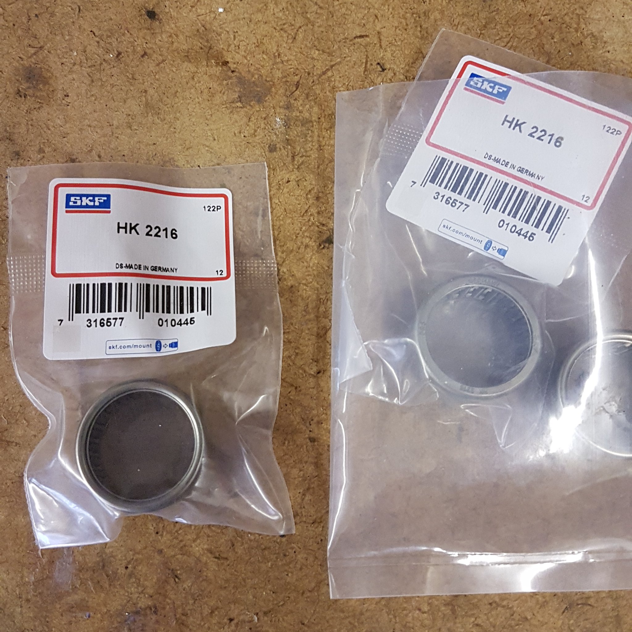
Also my 2mm wider high quality needle roller bearings have arrived, I will fit them next time I have the motor apart. Does anyone know the best way to disconnect the hall sensor?
------------------------------------------------
Also I would like to make my own throttle but I cannot make sense of the resistance readings I am getting from the stock Item. 10 ohm across one contact pair, 20 and 30 across the others.
Resistance does not change when the throttle is applied.
Is the throttle a variable resistor inside?
Does anyone know the range of values from zero to max throttle?
Aaaand, I have a gear sensor to fit.
I would like to use 2 brake sensors as well.
The 860C has no inputs for sensors.
I have had a search for the info on here but did not find it.
Does anyone have or could they make a very simple wiring diagram that shows a wiring loom with the following:
8 wire TSDZ2 controller
860C Display (same as 850 yes?)
Throttle
3 wire brake sensors x 2
3 wire gear sensor x 1.
I assume the gear and brake sensors wires all join, I just don't know where they go when they are joined...
Thank You.
Looking forward to trying the firmware as soon as my step up buck booster finally arrives from china!!! version 1.0 will be my first ever go!
I have improved axle play, now I realised from a video on here recently that someone has used feeler gauges already but this is not as great in the torque sensor/axle through hole.
The hardness of the materials means they may bind together. As some said it is better than nothing.
Different people may have different problems. I suspect that the parts are all different sizes, this is what happens when things are made to a price level not a quality standard. Some do not wobble at all probably. I do not think it makes any difference if you buy from Europe, America or China. Same factory, same machine, same operator. Maybe there are special arrangements. I think probably not. Anyway, we have very, very cheap ebikes that may be 1/10th the price of a powerful purpose built machine so we improvise.
Here are my issues with moving pedals.
Micrometer measurement, Non drive side - 14.88mm, 0.12mm undersize. This is why the ball bearing is loose on the shaft.
Measurement on drive side is actually VERY close to 15mm meaning Torque sensor hole is likely oversize.
Picture showing why the axle wobbles. this is why my pedals feel like they are moving left to right instead of only round and round.
Here is my proposal, it has not been tested over a long period of time on this application. hopefully it will work O.K.
Non-Drive side, Feeler gauges:
Drive side, Nylon or PTFE Wafer + Heat gun + sandpaper:
I had to have several attempts to properly attach the nylon here, it is tricky and although it stuck very well in the end, this may not last forever. This picture shows an early attempt, in the end I refined the system by making wafers of nylon with a hand plane, heated them with a heat gun until they melted enough to adhere to the axle then sanded them down until they were very, very thin. You have to be careful inserting and removing the axle, it interferes with the wires from the hall sensor. Don't push too hard, you might break the wires, a little twist may help, taking it out and gently flattening the wires inside the torque sensor with a screwdriver so they do not protrude into the hole can help sometimes . When sanding down the nylon bit by bit try test fitting through the other end until you have a good fit, not constantly pushing the axle all the way through the torque sensor to test.
Also my 2mm wider high quality needle roller bearings have arrived, I will fit them next time I have the motor apart. Does anyone know the best way to disconnect the hall sensor?
------------------------------------------------
Also I would like to make my own throttle but I cannot make sense of the resistance readings I am getting from the stock Item. 10 ohm across one contact pair, 20 and 30 across the others.
Resistance does not change when the throttle is applied.
Is the throttle a variable resistor inside?
Does anyone know the range of values from zero to max throttle?
Aaaand, I have a gear sensor to fit.
I would like to use 2 brake sensors as well.
The 860C has no inputs for sensors.
I have had a search for the info on here but did not find it.
Does anyone have or could they make a very simple wiring diagram that shows a wiring loom with the following:
8 wire TSDZ2 controller
860C Display (same as 850 yes?)
Throttle
3 wire brake sensors x 2
3 wire gear sensor x 1.
I assume the gear and brake sensors wires all join, I just don't know where they go when they are joined...
Thank You.
Looking forward to trying the firmware as soon as my step up buck booster finally arrives from china!!! version 1.0 will be my first ever go!
")