izeman
1 GW
Shame. Didn't look at the screw it self. Not that I could have read it without magnifying glasses anyway. ") Thanks!
Thanks!
I'm not using the supplied cranks, as I had to shorten mine because of the 20" rims I use in my former 26" bike. Could be that the Tongsheng taper is not exactly the same as the original Shimano one. Didn't think of that before. I'm totally aware how tapers are supposed to work, but neglected the fact that improper production could be the issue.
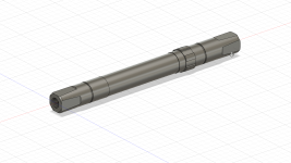
Maybe I'll try Helicoil once the thread gets really striped. I may also get longer bolts/screws as the threads on my axle are really deep. Still don't you think that it will weaken the axle even more? There is not much material and the hole and thread you need to drill for an M8 Helicoil is quite large.
Thanks!I'm not using the supplied cranks, as I had to shorten mine because of the 20" rims I use in my former 26" bike. Could be that the Tongsheng taper is not exactly the same as the original Shimano one. Didn't think of that before. I'm totally aware how tapers are supposed to work, but neglected the fact that improper production could be the issue.
Maybe I'll try Helicoil once the thread gets really striped. I may also get longer bolts/screws as the threads on my axle are really deep. Still don't you think that it will weaken the axle even more? There is not much material and the hole and thread you need to drill for an M8 Helicoil is quite large.