New "TSDZ2 Torque Sensor Central Motor"

In case anyone is interested here is our new "dirt cheap" battery which cost $50 total for all 3 new 20v5ah Harbor Freight Hercules batteries plus some wire and connectors. I bought them on ebay when the 20% coupon was going around. Inside there are 30 (15s2p) Samsung Inr18650-25r M cells rated at 2500mah and 20a rated discharge each. Together the batteries make up one 56v 5ah battery, and it is 9" x 5" x 2.75" and weighs about 4.5lbs and fits in our handlebar bag. Eventually I will wire in a new 15s bms but for now they must remain intact due to lithium battery travel restrictions.

If I wasn't moving overseas in the future I would have bought 6 of them and wired them into one 15s4p 56v 10ah battery for $130 in parts. I think the way that they are designed allows the solder attaching them to be removed from the bms and then just drill into the plates and attach small screws to wiring terminals connecting them to the new 15s bms, so no soldering.

 
John and Cecil you should use some 12awg silicon wire and gold bullet connectors that are soldered on. Check out hobby king
 
jbalat said:
John and Cecil you should use some 12awg silicon wire and gold bullet connectors that are soldered on. Check out hobby king

The wires are 14awg. You do realize that the power leads on the motor are 16awg? Thus whatever battery you plug in will be running through 16awg wires before it reaches the motor. I really do not see much of a difference between the 16awg on my 58.8v max battery and the 14awg on the 63v max battery. I looked online and 14awg copper wire is fine for 16a (up to 20a supposedly), and the way we ride the motor rarely draws 16a. Am I missing something? I am not too good with electrical stuff.
 
John and Cecil said:
jbalat said:
John and Cecil you should use some 12awg silicon wire and gold bullet connectors that are soldered on. Check out hobby king

The wires are 14awg. You do realize that the power leads on the motor are 16awg? Thus whatever battery you plug in will be running through 16awg wires before it reaches the motor. I really do not see much of a difference between the 16awg on my 58.8v max battery and the 14awg on the 63v max battery. I looked online and 14awg copper wire is fine for 16a (up to 20a supposedly), and the way we ride the motor rarely draws 16a. Am I missing something? I am not too good with electrical stuff.

Yep 14awg is good enough for short distance (up to 60cm is my gut feel) but if you are running to the handle bars then use 12awg. Cut your wires as short as possible close to the motor since 16awg is too small. The silicon wire stuff is a little more flexible and can handle heat better. Soldering to gold connectors will give you less resistance. Crimping is not really the way to go with this high power stuff.
https://hobbyking.com/en_us/turnigy-pure-silicone-wire-12awg-1m-red.html
https://hobbyking.com/en_us/3-5mm-3-wire-bullet-connector-for-motor-5pairs-bag.html
 
Thank you Jbalat. There is not much I can do at the moment though, I already sold my soldering guns. Actually you would laugh if you saw how I wired the wires inside the battery. The battery has squeeze terminals for the plus and minus connections, I just stuffed the wires in backwards through them and then bent the stripped portion around the side of them. Then I replaced the plastic housing and screwed it together and the pressure from the screws and the snugness of the plastic around the terminals keeps the wires tightly in place. I don't think soldered silicon wire and gold connectors are going to help much when the wires are just resting up against the terminals. :lol:

I chose to do it this way so they can be taken apart and everything removed, and then they will be completely stock. I can have them ready for air travel in maybe 10 minutes total time:) They are rated at 92wh each so supposedly they are good to go inside the cabin. And when we land they can be reassembled in the airport without special tools.

The extension wires are about 3' long. Considering I am in the upper rpm range nearly all the time I don't think we are drawing even 10a most of the time. The wires and the battery are not getting very warm, even the 16awg wires are not getting warm.

I told you I am not good with electrical stuff!
 
jbalat said:
eyebyesickle said:
Nice! Thanks for sharing!
You made me curious again. I will retry going from 10s to 14s on my 36v and get some real data and maybe some video.

Ok tried 10s and 14s in both of the cases the cadence was limited by the max overspeed erps value of 580 to about 112rpm. The PWM duty cycle was around 210 with a max of 254.
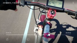
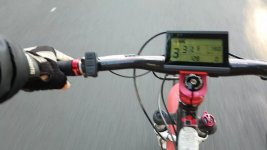
With 10s I could do around 43 and 14s I did around 46km/hr using 550w as the limiting power. The pic below shows 107 cadence so I probably should have gone to 600w to reach the limit.

I will boost the overspeed value up to 650erps and that will mean we will hit the limit of motor current first
 

Attachments

  • IMG_20180825_21298.jpg
    IMG_20180825_21298.jpg
    56.2 KB · Views: 2,585
Do you know what the cadence (rpm) limit is for the original firmware for the 52v motor? I assume I must be getting close to it now. I wish I could try the 62v today but it is already dark and my 20w china charger has got another 30 mins until the battery is charged up to 62v. Maybe I will try a quick spin up the street just to see if it kicks. :)
 
Ok well I tried 62v. I think it bucked on me for about a second but then took off running. I made 3 runs up and down my street and then measured voltage at 61.7v so it was at 62v. It was flying however I did not have fat little Cecil in the back this time. 14mph at 62v = 130 calculated cadence. My other numbers are probably off as those cadence numbers would probably be higher without the 25lbs of dog sitting directly over my rear wheel.

62v is a go! 8)

I think when the charger arrives I will see if I can get it to charge at 61.5v. That is 4.1v per cell, and they can be run down to 45v which is 3v per cell. That should be optimal range plus slight undercharging should increase the battery life a bit. If this continues to work it looks like the 15s option may be the best of both worlds, since you get the lvc of the 52v battery but nearly the full charge of the 56v battery thrown in as a bonus.
 
Would be good if you could validate the cadence. At 112 my legs were spinning pretty fast. Can't imagine 130.
 
jbalat said:
Would be good if you could validate the cadence. At 112 my legs were spinning pretty fast. Can't imagine 130.

Yeah I don't know. I am using tire and gear calcs to come up with that, plus whatever tire size I set in the lcd (provided that is even correct). I really need a gps but I sold it with my car. I know at 48v it is supposed to push aprox 90 cadence or so, and 62v is 130% of 48v. 130% of 90 = 117. Maybe it is only 120 cadence, and I wasn't even pedaling I was just using the throttle but it was moving and I was only in 1st gear. It felt more like 3rd gear :) I think it might have just as much to do with Cecil not being with me too though.

About the best I can do is more accurately test it at 62v and 48v without Cecil, and then if someone has an accurate stock cadence number for 48v then I can use that to figure out the 62v cadence.

Oh, maybe when I flashed it the tire size changed. :( I will go check that now.

Ok, my tire size is set at 29'er. I did that because I am using 27.5 x 2.8 plus tires. I believe the 29 size is closer than any of the other settings. I checked bike calc and a 29 x 2.4 tire would show an increase of speed of about .4mph at 14mph. That means I was probably really going about 13.5 mph. Even I drop the speed to 13mph (1 mph less) to do the calc I am still getting about 125 cadence.
 
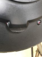
Attempting to reduce the awful whining noise my TSDZ2 makes, I re-greased the secondary reduction gears (it hasn't made much difference). On disassembly, I found the run-out of the chain ring is so bad it has worn partway through the plastic cover.
IMG_0202.jpg
IMG_0203.jpg
I have spaced the chainring out by 1mm with washers which makes for a static clearance but the deflection in the bearings & shaft cause a light touch when pedalling hard. Anyone else found this?

I have 500km on this motor (still on a nylon gear) and the vibration through the frame is driving me bonkers. It isn't much worse than the Youtube videos but compared to my 8,000km BBSHD, it is unacceptable. I made a plastic rear motor support to replace the supplied one so the only point of frame contact is the BB. Not impressed.
I have a Lingbei on order now.
 
Just removed all the limitations from the open-source firmware and I got 120 max cadence at 10s and 128 max at 14s so yes it's possible you can get to 130 with 15s ;)
In both cases tge motor was at max duty cycle and it makes sense that this increases with voltage

Variables changed
Erps overspeed is now set to 700
max pas cadence is set to 130
 

Attachments

  • IMG_20180825_29523.jpg
    IMG_20180825_29523.jpg
    36.4 KB · Views: 2,539
Thanks guys for all the info.

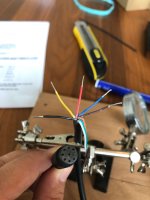
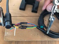
I just wired my kt-lcd3 cable up to the 8 pin cable of the motor see pictures below. (thanks casainho for the wire diagram on the wiki)

IMG_8665.jpeg
IMG_8666.jpeg
IMG_8667.jpg
View attachment 2
IMG_8674.jpeg

Then I tried to make programming cable but what a work :shock:

First i tried to make a standard higo 6 pin cable hoping that would fit on the sensor cable of the motor but what ever i tried it didn't fit.

View attachment 3

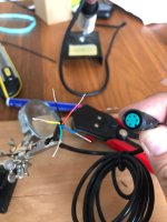
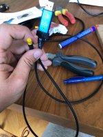
So then I cut my y-split sensor cable :cry: because i couldn't wait and made a programming cable of that. (thanks jbalat for the wire diagram). That was also a lot of work because the y-split connector had a small pcb which you need to de-solder.

View attachment 4
IMG_8678.jpeg

So now it is time to try to program the motor and then i will let you know my findings.
 
jbalat said:
Just removed all the limitations from the open-source firmware and I got 120 max cadence at 10s and 128 max at 14s so yes it's possible you can get to 130 with 15s ;)
In both cases tge motor was at max duty cycle and it makes sense that this increases with voltage

Variables changed
Erps overspeed is now set to 700
max pas cadence is set to 130


Cool, thank you. I can say that I can feel the difference between 14s and 15s. I can really feel the difference when I leave Cecil home too, fortunately for Cecil that almost never happens. :) My rear tire has worn completely through the middle knobs already and we only have 800 miles on it :( I hope I can find a 27.5 x 2.8 tire that will wear a lot better, I don't wish to change the rear tire every 1000 miles.

When I do change the tire I will probably swap the rear cassette with the 11-40 wide ratio and I may try dropping the front back down to 34t or 36t. Our calculated top speed in 8th gear (at 130 cadence) with the stock 42t chainring is now up to 42mph, even with a 34t it would still be 34mph. None of those speeds are possible for us without going downhill. I don't think the 110mm bolt pattern will allow anything smaller than a 34t chainring though.

We are going to give it a good ride today and see how it works. So far I am liking the increased power and increased range. I'm thinking I can get maybe 15 miles out of this little battery on turbo, especially considering I have 17 usable volts (62-45).
 
Mmm my program cable doesn't work. I get an error in ST visual programmer that it can communicate.

I installed my kt-lcd3 and connected it to the 8 pin connector of the motor.

Then I connected my program cable to speedsensor cable of the motor.
The cable is connected as below:


I tested the connection with my multimeter and they are correct.
Are the wiring connections correct (i assumed there was no difference between 6 pin and 8 pin motor for the programming cable)?

I also tried:
only 5v from stlink and batterry disconnected and 8 pin connected
only 5v from stlink and battery disconnected 8 pin not connected
without 5v from stlink and battery connected and 8 pin connected
without 5v from stlink and battery connected and 8 pin not connected

I don't know how you guys normaly program the motor.

Any ideas what goes wrong or what I can do as a next step to test?
The programming of the lcd was not a problem is the stlink should be fine.
 
bart1006 said:
Mmm my program cable doesn't work. I get an error in ST visual programmer that it can communicate.

I installed my kt-lcd3 and connected it to the 8 pin connector of the motor.

Then I connected my program cable to speedsensor cable of the motor.
The cable is connected as below:
program_cable_wiring2.jpeg

I tested the connection with my multimeter and they are correct.
Are the wiring connections correct (i assumed there was no difference between 6 pin and 8 pin motor for the programming cable)?

I also tried:
only 5v from stlink and batterry disconnected and 8 pin connected
only 5v from stlink and battery disconnected 8 pin not connected
without 5v from stlink and battery connected and 8 pin connected
without 5v from stlink and battery connected and 8 pin not connected

I don't know how you guys normaly program the motor.

Any ideas what goes wrong or what I can do as a next step to test?
The programming of the lcd was not a problem is the stlink should be fine.

Yeah dude, it is called cheap china made stuff. It happened to me when I tried to read or write the original program and memory files to the stock controller. I ended up doing one at a time, and I would try like 10 times in succession. If it didn't work I would hook the battery up to the controller and occasionally turn the display on and off. Sometimes pressing the power button on the stock lcd helped without the battery hooked up after it gave me the error, or maybe it was just coincidence. Anyway try a few dozen times with just a single function and see if it will eventually sneak one through.

I also tested my wires and they were perfect, however my wiring job was not as polished as yours! Just keep trying and only do one function at a time. After it writes the verification will probably fail due to the communication error. You will have to verify manually. I paid $2 for mine on aliexpress so I guess I got what I paid for, and mine looks exactly like yours!
 
I got a cheap programmer too. I installed the drivers from eyebyecicles guide.
https://www.eco-ebike.com/blogs/eco-cycles-instructionals/tsdz2programmingfromscratch

Did you manage to flash the ktlcd3 first ? If that worked then maybe it’s not the drivers ?
 
jbalat said:
I got a cheap programmer too. I installed the drivers from eyebyecicles guide.
https://www.eco-ebike.com/blogs/eco-cycles-instructionals/tsdz2programmingfromscratch

Did you manage to flash the ktlcd3 first ? If that worked then maybe it’s not the drivers ?

Yes no problem with the LCD3 so probably not the drivers.
 
John and Cecil said:
... Anyway try a few dozen times with just a single function and see if it will eventually sneak one through.

Will keep trying ;)
Do you have a long or a short programming cable? My one is prettig long maybe that can be an issue?
 
I used the speed sensor extension cable. I have about 2 feet of wire between the plug and the stlink. Maybe that is why mine is so flaky!
 
Well we took another ride today, I guess we started out about 61.5v with the 15s battery. It is working perfectly. I have noticed a decent increase in both speed and power over the 14s battery. This may be due to several factors though, since the 15s battery has a 2p configuration (cells rated at 20a continuous) and more than double the ah's, and the 14s is a 1p config (cells 20a continuous each). Also the 15s2p battery is wired with 14awg wire and the 14s1p battery is 16awg. I assume all 3 of these factors may be contributing to the increase in power. Today we took our usual ride and on a short 10-12% +/- hill I normally need to pedal moderate/hard on a full charge and hard on a low charge but today we went up it with only light pedaling.

The charger is being a pain due to having to charge each battery separately for several hours but I think I can hook all 3 batteries up parallel and then charge them all together overnight. If so I will continue to test the motor with the 15s battery undercharged by 1 to 2v's. Actually I believe I can run it at full charged 15s battery by kicking the throttle, but I am not sure how good it is for the capacitors to run at 63v's as that is their actual rating.
 
bart1006 said:
Do you have a long or a short programming cable? My one is prettig long maybe that can be an issue?

That could be the problem.
My cable was also too long, but for flashing the LCD3.
 
bart1006 said:
jbalat said:
I got a cheap programmer too. I installed the drivers from eyebyecicles guide.
https://www.eco-ebike.com/blogs/eco-cycles-instructionals/tsdz2programmingfromscratch

Did you manage to flash the ktlcd3 first ? If that worked then maybe it’s not the drivers ?

Yes no problem with the LCD3 so probably not the drivers.
For TSDZ2 motor controller, try to not wire the 5V wire to the STLinkV2 clone, wire only the other 3. Then, program with the TSDZ2 powered on.
 
I just made my cable a lot shorter like (10cm) and now it works like a charm!
So maybe this is also something to add to the wiki casainho.
 
bart1006 said:
I just made my cable a lot shorter like (10cm) and now it works like a charm!
So maybe this is also something to add to the wiki casainho.
Good! I will, let's see if I do not forget.

Now, please configure correctly all the options on LCD3. Which motor voltage are you using? Did you flash the correct hex file?
 
Back
Top