Seeking Help: BLDC Motor Control Board Development (FOC Technique)

BldcLover

1 mW
Joined
Mar 23, 2025
Messages
14
Location
BldcLover@123
Hi everyone,

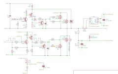
I am designing a BLDC motor control board using the Field-Oriented Control (FOC) technique. I have completed some parts of the design and tested certain sections successfully.

Here is the my Github repo: GitHub - BldcLover/TransistorDrivenInverter at Implementations

I am planning to use the STM32F103C8T6 for control, but I haven’t placed it in the design yet. I will be adding it later. Right now, I need help with:

:small_blue_diamond:
Inverter section – Verification and improvements
:small_blue_diamond:
Shunt selection & configuration – Ensuring accurate current sensing

I have follow current sense section from VESC

If you have experience with BLDC motor control, power electronics, or FOC implementation, I’d really appreciate your insights. Looking forward to your feedback and suggestions!

Thanks in advance!
BldcLover
 
Last edited:
Hi stancecoke,

Thank you for your suggestion! I appreciate the references to the EBiCS firmware and hardware files.

I have gone through both the firmware and hardware files, and I have some questions regarding the hall angle detection in the autodetect function. From what I understand, the motor is rotated in open loop by setting Id to a fixed value and Iq to zero.

Here’s my understanding of the process:
- Initially, the angle is set to 180 degrees at the mid-level, and the motor starts rotating in open loop.
- The angle is then incremented by approximately 0.5 degrees in a loop, rotating the motor around 1080 degrees (360 × 3).
- When a hall state change is detected, the current angle value is assigned as the hall angle.

My question is: How do we determine if the assigned angle is correct?
- Could it be that the selected angle leads to higher, lower, or optimal current consumption?
- What parameters should we consider to ensure that the assigned hall angles are accurate?

Additionally, I am working on designing a low-cost BLDC controller, and I am incorporating certain elements from the existing designs, except for the current sensing and MCU selection.
- Instead of using a traditional driver, I have implemented transistor-based logic.
- Since current sensing is critical, I am using INA240.
- For the MCU, I am considering STM32F1 or STM32G431.

I would appreciate your insights on this! Thanks again for your help.

Best regards,
BldcLover
 
How do we determine if the assigned angle is correct?
The procedure is quite simple in theory and works quite stable. The only case where it failed is discussed in the Lishui thread recently.
We discussed the strategy on various platforms, especially @mxlemming is very experienced here. The conclusion is, the motor runs best in sensorless mode, as the observer has no problems with latency, mechanical inaccuracies....
EBiCS has implemented three strategies to estimate the rotor position:
- hall sensor based angle extrapolation
- hall sensor based PLL
- sensorless observer, simplified version of the "old" VESC observer. I never tried to adapt @mxlemming 's new VESC/MESC observer...
My experience: I'm happy with the simple extrapolation;)

regards
stancecoke
 
Last edited:
Hi Stancecoke,

I have a geared BLDC sensored motor and have attached the PDF file for your reference.

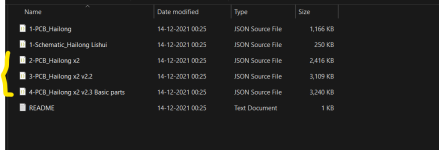
I am planning to use the PCB design you shared via the GitHub link. However, I noticed that there are two PCB files available. Could you please clarify which one I should use?

Additionally, I would like to know which your firmware branch is suitable for this board.

I will also continue developing my own design as part of my learning process, but using this board will help me gain a better understanding.

Looking forward to your response.

Best regards,
Bldclover
 

Attachments

  • cycle_motor_document (1).pdf
    310 KB · Views: 0
  • multiplePcbFiles.png
    multiplePcbFiles.png
    26.3 KB · Views: 1
Hi stancecoke,

Thank you for your suggestion! I appreciate the references to the EBiCS firmware and hardware files.

I have gone through both the firmware and hardware files, and I have some questions regarding the hall angle detection in the autodetect function. From what I understand, the motor is rotated in open loop by setting Id to a fixed value and Iq to zero.

Here’s my understanding of the process:
- Initially, the angle is set to 180 degrees at the mid-level, and the motor starts rotating in open loop.
- The angle is then incremented by approximately 0.5 degrees in a loop, rotating the motor around 1080 degrees (360 × 3).
- When a hall state change is detected, the current angle value is assigned as the hall angle.

My question is: How do we determine if the assigned angle is correct?
- Could it be that the selected angle leads to higher, lower, or optimal current consumption?
- What parameters should we consider to ensure that the assigned hall angles are accurate?

Additionally, I am working on designing a low-cost BLDC controller, and I am incorporating certain elements from the existing designs, except for the current sensing and MCU selection.
- Instead of using a traditional driver, I have implemented transistor-based logic.
- Since current sensing is critical, I am using INA240.
- For the MCU, I am considering STM32F1 or STM32G431.

I would appreciate your insights on this! Thanks again for your help.

Best regards,
BldcLover
Use the MCU that's native to the code base you want to run...
Ebics? Stm32f1
VESC? Stm32f405rg
Mine? Stm32f405, l431, f411...
Writing your own? Pick something with a floating point unit and at least 10adc inputs.

If you can, get an ABI encoder and wire it into a timer on the stm (timer2,3 or 4)

If you have to use hall sensors, best look at the ebics... The STM library hall sensor is a bit of a head game and didn't work well for me.

Sensorless observer is like 20 lines of code, trivial if you have managed to get the rest of your FOC under control. Impossible if you have decided to use hacked units and have no time base.

Ina240 but save a few pence on gate drivers? Why make your life hard...

Good luck.
 
Hello everyone,

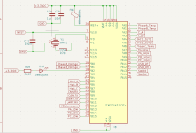
I have updated the schematic and selected the STM32G431C6T6 MCU (48-pin).

I have shared a schematic image detailing the pin connections, along with an Excel file for reference. Please review it and provide any feedback on the pin selection.

Note: Peripheral connections have not been designed yet; this update only covers MCU pin assignments.
1743100015261.png
MCU_PIN_SELECTION
 
Use the MCU that's native to the code base you want to run...
Ebics? Stm32f1
VESC? Stm32f405rg
Mine? Stm32f405, l431, f411...
Writing your own? Pick something with a floating point unit and at least 10adc inputs.

If you can, get an ABI encoder and wire it into a timer on the stm (timer2,3 or 4)

If you have to use hall sensors, best look at the ebics... The STM library hall sensor is a bit of a head game and didn't work well for me.

Sensorless observer is like 20 lines of code, trivial if you have managed to get the rest of your FOC under control. Impossible if you have decided to use hacked units and have no time base.

Ina240 but save a few pence on gate drivers? Why make your life hard...

Good luck.
Hi mxlemming,

Thank you for your detailed response! I really appreciate your insights.

I understand the importance of choosing an MCU that aligns with the firmware I plan to use. Based on your suggestions, I’ll carefully evaluate the best option for my application. The idea of using an ABI encoder with a timer is definitely something I'll consider, as it could improve performance and accuracy.

Regarding Hall sensors, I’ll take a closer look at EBiCS, and if needed, explore alternative methods like a sensorless observer once I have a stable FOC implementation. I completely agree that reliable current sensing and proper gate drivers are crucial—I’ll make sure not to compromise on those aspects.

Thanks again for your guidance! I’ll keep refining my design and will update as I progress.


Best regards,
BldcLover
 
Last edited:
Hello, BldcLover I am working on a project EXACTLY like yours, but I have no clue where to start which is why I am checking through forums, is there anyway you could give me some pointers as to where to look for information and how to find what tools I will need. I hope you have a great day!
 
Use the MCU that's native to the code base you want to run...
Ebics? Stm32f1
VESC? Stm32f405rg
Mine? Stm32f405, l431, f411...
Writing your own? Pick something with a floating point unit and at least 10adc inputs.

If you can, get an ABI encoder and wire it into a timer on the stm (timer2,3 or 4)

If you have to use hall sensors, best look at the ebics... The STM library hall sensor is a bit of a head game and didn't work well for me.

Sensorless observer is like 20 lines of code, trivial if you have managed to get the rest of your FOC under control. Impossible if you have decided to use hacked units and have no time base.

Ina240 but save a few pence on gate drivers? Why make your life hard...

Good luck.
I sincerely apologize; I mistakenly included the wrong username in my reply.
Use the MCU that's native to the code base you want to run...
Ebics? Stm32f1
VESC? Stm32f405rg
Mine? Stm32f405, l431, f411...
Writing your own? Pick something with a floating point unit and at least 10adc inputs.

If you can, get an ABI encoder and wire it into a timer on the stm (timer2,3 or 4)

If you have to use hall sensors, best look at the ebics... The STM library hall sensor is a bit of a head game and didn't work well for me.

Sensorless observer is like 20 lines of code, trivial if you have managed to get the rest of your FOC under control. Impossible if you have decided to use hacked units and have no time base.

Ina240 but save a few pence on gate drivers? Why make your life hard...

Good luck.
 
Hello, BldcLover I am working on a project EXACTLY like yours, but I have no clue where to start which is why I am checking through forums, is there anyway you could give me some pointers as to where to look for information and how to find what tools I will need. I hope you have a great day!
Hi Ilyane4,
You can start with the following key aspects when designing a BLDC motor controller hardware project:
1️ Understanding BLDC Motor Control Basics
- Learn about six-step commutation vs. field-oriented control (FOC).
- Understand PWM control, back-EMF sensing, and current sensing methods.

2️ Choosing the Right MCU
- STM32G4 series (like STM32G431) is great for BLDC control due to its high-speed ADC, PWM, and FPU.
- Consider hardware with built-in motor control features, like ST’s B-G431B-ESC1 board.

3️ Power Stage Design
- Select MOSFETs or IGBTs based on voltage/current ratings.
- Use a gate driver (e.g., IR2101, DRV8302, or some chinese low cost gate drivers availabel on LCSC).
- Choose a DC-DC converter for powering logic circuits (e.g., MP9486A).

4️ Current Sensing
- Shunt resistors (1-5 mΩ) + INA240 current sense amplifier (for precise phase current measurement).
- Use an isolated or hall-effect current sensor if needed.

5️ Firmware & Development Tools
- Use STM32CubeIDE + Motor Control Workbench for development.
- Implement PWM generation, ADC sampling, and PID current control.
- Learn FOC (Field-Oriented Control) if you want smoother performance.

6️ Simulation & Testing Tools
- Oscilloscope & logic analyzer are essential for debugging PWM, current signals, and USB communication.

7️ Reference Materials
- Read ST's motor control application notes.
- Look at open-source ESC projects (like VESC) to understand hardware + firmware design.
 
Hello everyone,

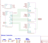
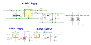
I’ve updated the schematic. Please take a look and let me know if you notice any mistakes or anything that needs improvement.

Best and regards,
BldcLover

1743800568523.png
1743800579331.png1743800595620.png1743800617038.png
 

Attachments

  • TTLDrivenInverter.pdf
    240.5 KB · Views: 0
Hello everyone,

I’ve updated the schematic. Please take a look and let me know if you notice any mistakes or anything that needs improvement.

Best and regards,
BldcLover

View attachment 368304

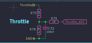
Why 3,3V throttle ? Have you seen a 3,3V throttle being used in some bike? I've assumed it's not because
those are made by chinese, that the voltage range those usually operate on is somewhere from 1V to 4V
out of 5V.

edit: my point was, someone(atleast i do) might consider it a safety feature, to go w/the usual 5V throttle.
 
Last edited:
Why 3,3V throttle ? Have you seen a 3,3V throttle being used in some bike? I've assumed it's not because
those are made by chinese, that the voltage range those usually operate on is somewhere from 1V to 4V
out of 5V.
Hi aae34,

You're absolutely right — I had placed it incorrectly by mistake. I've now updated it.

Thanks a lot for pointing it out!

-BldcLover

1743802502846.png

1743803422753.png
 
Last edited:
Hi Stancecoke,

I hope you're doing well.

I’m quite new to STM32 development and I’ve installed Eclipse and imported the EBiCS firmware project, but I haven’t been able to build it successfully. I also tried importing it into STM32CubeIDE, but it says "nothing to build."

Since I’m still learning, I’m not sure if I’m missing some important setup steps. My goal is to understand how the firmware works so I can eventually adapt it for my own future hardware design.

Would you mind guiding me through the process of building the project? Any help or suggestions would be greatly appreciated.

Thank you so much for your time and for sharing this amazing project.

Best regards,
BldcLover
1743871900523.png
 
Did you follow the tutorial in the Wiki step by step?

https://github.com/EBiCS/EBiCS_Firmware/wiki
Hi Stanceoke,

I hope you're doing well.

Thank you so much for your earlier help. I came across one of your responses in the community forum where you were helping someone with a similar issue — from that conversation, I found a very helpful link and a note about checking the spam folder for the verification email. That tip worked perfectly, and it really helped me get past that hurdle. Thank you again for sharing your knowledge so generously!

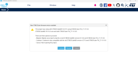
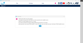
At the moment, I’m able to build the project successfully in System Workbench without any issues, which is great. However, I’m currently facing a challenge with the CubeMX `.ioc` file. Whenever I try to open it within the Eclipse IDE, I’m prompted with the "Migrate and Continue" message. I’ve tried both options, but unfortunately, CubeMX doesn't proceed beyond that point — it simply doesn't open the file.

The message also indicates that I need an older version of CubeMX to proceed. I’ve already tried using version 6.0, but it didn’t resolve the issue.

Would you be kind enough to guide me on how to properly open or migrate the CubeMX file within the same Eclipse IDE environment? I’d really appreciate any tips or steps you can share.

Thank you once again for all your help and for your contributions to the community.

Warm regards,
BldcLover

1743960495074.png
1743960526423.png
 
I’m currently facing a challenge with the CubeMX `.ioc` file
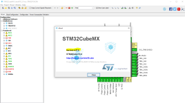
The .ioc in the repo can be opened and edited with Version 4.27.0. but you can't do anything with this .ioc file. I used CubeMX only for the very first setup of the peripherals, but later I changed a lot of settings manually directly in the code. So if you generate new code from the ioc file, you will overwrite all manual settings. At the moment I use CubeMX to draw that pretty pictures of the processors pin function only :)
There were many issues with various versions of the Cube MX code generator, I don't know, if it works properly in the CubeIDE meanwhile....

1743964488749.png
 
Last edited:
Your phase voltage only measures 2 phases... Surely you need 3. How bright do you need the debug led? Why so many test points? Why only measure 2 phase current? You sure pb12 is adc? I didn't check g431but none of the other stm32 has adc on pb12.

Some strange choices here ...
 
Hello everyone,

I’ve updated the schematic. Please take a look and let me know if you notice any mistakes or anything that needs improvement.

Best and regards,
BldcLover

View attachment 368304
View attachment 368305View attachment 368306View attachment 368307
Just saw you use the C6 version of chip. This will run out of memory and ram very quickly for running FOC... I think you can barely fit the stm32 initialisation code on it. Should use the CB version at least with 128kB.
 
This will run out of memory and ram very quickly for running FOC
It works, but you are right, there is not much free memory left. The EBiCS master works with 4k for the Bootloader and 2k for the virtual EEPROM, so there is only 26k left for the main code. It provides full four quadrant (sensorless) FOC operation.
The new generation of the Lishuis is using the C8.
Of course, if you want to develop your own hardware, you should use a type with more memory, as it is no cost factor, if you don't want to build millions of the controllers ;)
 
Last edited:
It works, but you are right, there is not much free memory left. The EBiCS master works with 4k for the Bootloader and 2k for the virtual EEPROM, so there is only 26k left for the main code. It provides full four quadrant (sensorless) FOC operation.
The new generation of the Lishuis is using the C8.
Of course, if you want to develop your own hardware, you should use a type with more memory, as it is no cost factor, if you don't want to build millions of the controllers ;)
My foc code is currently using about 100k but it's got usb and can stack and options for all kinds of sensors and sensorless.... About half of it is for the terminal netzpfuscher added (i think but not sure). Squeezing it onto a C6 micro sounds like no fun atall.
 
Your phase voltage only measures 2 phases... Surely you need 3. How bright do you need the debug led? Why so many test points? Why only measure 2 phase current? You sure pb12 is adc? I didn't check g431but none of the other stm32 has adc on pb12.

Some strange choices here ...
Hi mxlemming,

Apologies for the late reply — I was caught up with some things and couldn’t get back to work sooner.

Thank you for taking the time to review my schematic. I’ll go through it again and make the necessary updates. I’ve also created an Excel sheet where I’ve listed the details of each pin, based on which I selected them. However, I’ll recheck everything thoroughly to make sure there are no issues.

I’ve attached the Excel sheet for your reference, which includes all the pin details.

Thanks again for your support!

Best regards,
BldcLover
 

Attachments

  • STM32G431C6_PIN_DETAILS.xlsx
    12.9 KB · Views: 2
Just saw you use the C6 version of chip. This will run out of memory and ram very quickly for running FOC... I think you can barely fit the stm32 initialisation code on it. Should use the CB version at least with 128kB.
Thanks for pointing that out!


I chose the C6 version mainly due to availability and cost, but I completely understand your concern regarding memory limitations. I’ll definitely look into switching to the CB version with 128kB — having more headroom will be really helpful, especially as the project grows.


Appreciate the advice!
 
Hello everyone,

I’ve been trying to understand this concept for quite some time, but I’m still a bit confused — I’d really appreciate any insights you can share.

How does an op-amp measure negative current when using low-side current sensing?
I’ve done a lot of reading and research, but I’m still not entirely sure how it works in practice.

Specifically, I’m trying to understand:
  • In what situations does the low-side MOSFET conduct current [how opamp measure negative current?]?
  • When and how does the body diode conduct current back to the phase or to upper MOSFET body diode through body diode?
  • How is this reflected as negative current in the sense resistor and measured by the op-amp?
If anyone could help clarify this or point me to a good resource — like an article, application note, or video — that would be really helpful for my understanding. I’d be very grateful!

Thanks in advance!
BldcLover
 
Back
Top