speedict said:
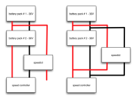
see attached diagram, it is similar to your proposed method, yes the voltage is 1/2 of the pack, however you can see on method 1 (left) no current flow through speedict that's mean no current measurement, on method 2 (right), "some" current will flow through speedict but we don't know the ratio of total current draw ...
and if you just tap one of your battery pack and let speedict scale up, it may not be accuracy enough because 2 battery may not be in same potential

why need absolute accurate of battery pack measurement ? it is our top question to solve and up to this moment we don't have solution because what is earth's reference voltage ? for 5v or under 10v it is easy by using some reference IC but for high voltage it is so difficult and the back to square one, can we find the reference voltage to calibrate our reference voltage
Not quite what i meant but close.
Referring to diagram 1, if the positive was say the common rail connection,
i'm still assuming there is one through one side? and the current sense is in the negative line, this is what i meant.
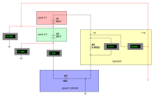
The 36V connection supplies the speedict's mA needs only and the full pack current still flows through speedict.
There are obviously other better methods of creating a lower voltage supply from a +100V pack to supply speedict's electronics, i'm not an EE, but i was thinking of immediate needs.
I'm wondering why it is difficult too, to monitor a higher voltage than speedict supply voltage.