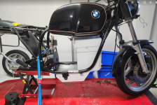
Street legal Cafe Racer build.

The plan is for the throttle, in fact all of the sensors, to come into a body control module. Ie the throttle will not connect to the drive at all.
The body control module will process the signals and send them to the drive, lights, bms, etc.. We haven't yet found a way to command throttle over the serial link to the Far Driver controller, so it may need to be that the BCM generates an analog throttle command.

Point is, between the throttle signal coming in and going out, you can do anything with it. You can adjust it to maintain constant power, constant speed, compensate for battery or temperature conditions. It's just a map.
Yes that's how I understood it, but the Fardriver also has its own map and PID control, which will be applied after your custom map.
Let's say that your map consists in being just ON/OFF --> then it's just the Fardriver default full throttle PID behavior
Then if your map is anything else, it can only make the throttle response softer than this, because whatever your input number is, it just can't be more than default full throttle anyway. Not even mentioning potential throttle delays, even though I admit the lag will likely be unnoticeable because your module shouldn't really be that slow considering it has relatively little work to do to process the signal and send it back.

At least that's my understanding right now, maybe I'm missing something.
I don't see how this could work properly without getting entirely rid of the internal Fardriver throttle control system. Unless if the point is to make the throttle response slower or softer, but I can't think of any reason why anyone would want to do that.

Sorry If I missed something and asked dumb questions, hopefully I didn't.
For the sake of the discussion, let's say we had a linear profile set up in the far driver. But we noticed that there was a delay in the drive ramping up the phase amps when we snap the throttle from 0% to 25%. We would program the body control module to detect that we had snapped the throttle open rather just rolled it to 25%. The BCM might then send a 50% throttle command to the drive for the 250-500ms it might take to get it to respond faster. Essentially we're adding an additional feed forward instruction.

In practice, motor drives have PID loops within PID loops. The lowest level is usually phase current (torque) where the PWM signal and other timing going to the FETS is altered to maintain a commanded current. Then you might have a loop to keep the rotor slip where the drive wants it to be (this is key to FOC), on top of that, there may well be a velocity loop commanding torque to maintain constant speed, on top of that might be an acceleration loop commanding velocity to ramp at a desired rate. We're really just talking about adding another PID loop.

Make sense?
 
Last edited:
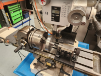
It feels good to be cutting metal. I got the gear blanks set up in the mill
and, "A FEW HOURS LATER"....

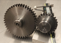
Still lots more to do on them but I measured them up and they will run with a 100 micron clearance. Waddya know, the maths works!
So...are you manually controlling the milling, or is that done by computer? (I know there are people that can do that work without a computer...but I couldn't!)
 
So...are you manually controlling the milling, or is that done by computer? (I know there are people that can do that work without a computer...but I couldn't!)
Oh that is just me sitting in front of the machine turning handles..... Fun times!

We have CNC machines (you'll see one when I cut the case) but gear cutting needs special set ups and I just don't do enough of it to justify the automation.
 
Right now I have a 30S ANT BMS. I'm going to use it for balancing the charged pack, I won't be running the discharge current through it.
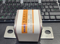
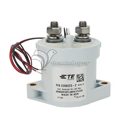
For safety I have a 1200A fuse, I'll monitor the battery current via the drive and open the contactor if it gets too high, and I also have some hall based current sensors. I'm toying with the idea of building an electronic fuse.
From my experience the 300A ANT BMS can take 550-600A peaks reliably.
Also, from my experience as well, it is possible to shunt mod it very easily. There are two shunts soldered on the bus bar and with a little bit of copper and solder you can have make a quick and dirty shunt mod so that it reads a lower current than the actual one. I did it on my black motorcycle just for the sake of experiment and it is now reading current 25% lower than it actually is.
Meaning in theory it could go up to 750A. But I haven't had the chance to test it up to such high currents unfortunately, my battery and motor aren't up to the task.

The ANT BMS Fets are pretty decent, at least on the versions I have. They can usually take a lot of abuse and don't really heat all that much. I wanted to replace them with something better but really couldn't find components that were worth the trouble. Not sure if this applies to the 30S version though, mine were 24S.

I wouldn't use a contactor as most of them are crap and tend to fail closed (mosfets do as well, but at least they don't weight a lot and they don't take valuable space). A friend of mine tried many of em from reputable EV brands and ultimately none worked properly, all of them welded shut. Very disappointing, I wonder how these things even pass safety tests.
A fuse is always a good idea though.

I think that if I had your electronics background I'd simply mod the ANT BMS and make my own power stage. It's not very difficult to do especially now that we have companies like JLCPCB and the likes that can make the board for you, it will be a lot more compact and lighter than any other solution, while providing the same if not greater level of safety. You can even deport the power stage far away from the logic stage so that if it fails it won't fry the brains, plus you could put it somewhere convenient for cooling and whatnot. That's what I'd do if I had a nicer battery/motor capable of such power.
 
I think that if I had your electronics background I'd simply mod the ANT BMS and make my own power stage. It's not very difficult to do especially now that we have companies like JLCPCB and the likes that can make the board for you, it will be a lot more compact and lighter than any other solution, while providing the same if not greater level of safety. You can even deport the power stage far away from the logic stage so that if it fails it won't fry the brains, plus you could put it somewhere convenient for cooling and whatnot. That's what I'd do if I had a nicer battery/motor capable of such power.
I have a couple of closed loop hall sensors good for 1500A. I'm thinking of using two in a redundant configuration and building an electronic fuse. That would involve either FET switches or some pyro actuated electro mechanical setup. Not much is going to survive opening a 1200A DC circuit with an inductive load. I probably won't do it unless the fuse proves unreliable.

I'm not really interested in the BMS for anything other than top balancing.
 
For the sake of the discussion, let's say we had a linear profile set up in the far driver. But we noticed that there was a delay in the drive ramping up the phase amps when we snap the throttle from 0% to 25%. We would program the body control module to detect that we had snapped the throttle open rather just rolled it to 25%. The BCM might then send a 50% throttle command to the drive for the 250-500ms it might take to get it to respond faster. Essentially we're adding an additional feed forward instruction.

In practice, motor drives have PID loops within PID loops. The lowest level is usually phase current (torque) where the PWM signal and other timing going to the FETS is altered to maintain a commanded current. Then you might have a loop to keep the rotor slip where the drive wants it to be (this is key to FOC), on top of that, there may well be a velocity loop commanding torque to maintain constant speed, on top of that might be an acceleration loop commanding velocity to ramp at a desired rate. We're really just talking about adding another PID loop.

Make sense?
Yeah that makes sense, that's pretty much what I understood already.
I think it will work for making the map more editable, but ultimately the default PID control of the Fardriver remains the hard limit.
I can see it working for mid range of the throttle, but I don't see how things like full throttle start from standstill could be improved with this method.
Anyway, it's not a big problem, the default fardriver throttle response is actually pretty good (at least when you get the correct firmware)
Dougs WR has a 961800 in it and, on the road, I quite liked the sport mode.
TBH I'm more interested in having the option for things like adaptive cruise control.
 
Oh that is just me sitting in front of the machine turning handles..... Fun times!

We have CNC machines (you'll see one when I cut the case) but gear cutting needs special set ups and I just don't do enough of it to justify the automation.
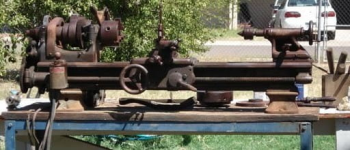
The ancient (nearly century old) lathe I've got had a box of assorted gears with it when I got it that I think are for thread-cutting, but I never got to investigating that (i've only used it a few times here and there, but its' been invaluable for those times I needed it!). I recall from the equally-ancient training films southbend had on their historical website as videos back then showed one of their lathes cutting gears using some added hardware, and it was discussed in the "manuals" too, but I can't remember any of the details of it, and I am certain that mine does not have all that hardware....
 
The ancient (nearly century old) lathe I've got had a box of assorted gears with it when I got it that I think are for thread-cutting, but I never got to investigating that (i've only used it a few times here and there, but its' been invaluable for those times I needed it!). I recall from the equally-ancient training films southbend had on their historical website as videos back then showed one of their lathes cutting gears using some added hardware, and it was discussed in the "manuals" too, but I can't remember any of the details of it, and I am certain that mine does not have all that hardware....
The lathe is the most useful of machines. It was the first machine tool that made all the others. Gear cutting is always a milling operation ( machine turns tool against stationary job) though. You can do it in a lathe if you put the cutter in the chuck and some kind of dividing head on the toolpost I guess.
 
Last edited:
The lathe is the most useful of machines. It was the first machine tool that made all the others. Gear cutting is always a milling operation ( machine turns tool against stationary job) though. You can do it in a lathe if you put the cutter in the chuck and some kind of dividing head on the toolpost I guess.
Unfortunately, I don't remember what they were doing...I wasn't paying enough attention, didn't know how any of it worked, and it was also well over a decade ago. :oops:

I did a quick look around and found this thread on how to make a cutter to make your gear,
though I didn't find the stuff I recall about using the SBL to actually make the gears (I could even be misremembering and conflating making gears with making screws...)

BTW, I found the post with pics and info of mine, below; it was a rustbucket when I got it and I have only done enough work on it to let it function, not restore it:
https://endless-sphere.com/sphere/t...amberwolfs-crazybike.17809/page-2#post-267791
1705464845578.png


Sorry for the OT... :oops:
 
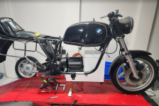
OK, first attempt at a battery box mockup...
battery 1.png
Yeah...nah. ... I've got some work to do here. I was thinking of adding a little chin scoop....
 
Can you go up and into the tank, if you cut the bottom of the tank out?
Yes, there's actually heaps of room. The volume of that polystyrene block will hold 600 cells!
What I'm trying to balance here is:
  • Keeping the CG low.
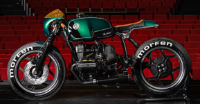
  • Paying some homage to the aesthetics of the bike. Cafe racer versions of the R80 typically include an air gap between the motor case and the tank.
1705526212716.png
  • Not making the battery box look like, well, a box. This is IMHO a problem with a lot of e-bikes.
  • Ending up with a cell pack that I can actually connect as 27P22S
I'll get there, it's just going to take a few iterations.
 
Aaaand we have batteries:
batteries arrive.png
The made it through customs so that's a landed cost of USD3.58 per cell.

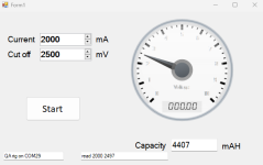
I have one on the battery tester now checking they are the real deal.
 
And they seem like the real deal
battt test1.png

I'll set up to measure the internal resistance tomorrow. Just to be sure...
 
OK, first attempt at a battery box mockup...
View attachment 346148
Yeah...nah. ... I've got some work to do here. I was thinking of adding a little chin scoop....
Great to see the project coming along, can't wait to see it rolling around.

Since you asked, my .02 on the battery... as mentioned, it sure would be nice if the box followed a bit more of an organic flow. Possibly could be done with add-ons like the chin scoop you mention. It would be more work, but since making the battery from scratch, possibly relocate some cells to allow rounding the corners and maybe make the front follow the down-tube angles a bit. The top/bottom/front could also be a bit convex to sort of mirror the gas tank form. Possibly even break it down into several packs resembling some other engine components / oil / coolant tanks, etc. Again, more complex on the wiring side, but separate packs might be better from a cooling standpoint than one monolithic block.
Thanks, and I did ask.
The challenge here is to follow the lines of the bike and still end up with a buildable battery.

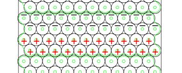
I should, perhaps, clarify 'buildable'. This pack will have a rated capacity of 900A. I'm going to run it at 700A peak, this means that I need a lot of copper between each of the 27 groups of parallel cells to pass this current with minimal loss and heating. I'm aiming for around 150mm^2.

In a box configuration this is simple because the series links are wide
1705617980625.png
In this case the series link is the copper between the + and - cells. Its 232mm wide, so I can use 0.75mm thick copper and have 175mm^2 to flow the angry electro-pixies through.

The more organic the shape of the pack gets, the harder it is to keep these series links wide. Now you can use tricks like wrap the copper around the edges of the pack, and you can just use thicker copper either everywhere, or just in places. But it gets complex quickly.
 
I get your point and it seems well thought out. Certainly many competing design goals when working with something custom. You mention 175mm² copper plates. Given copper resistivity around 1.7x10⁻⁶ ohm-cm, that is going to be orders of magnitude less resistance than other components in the system. So even if you have to add a bit more length, it won't materially change the performance.

That might be a fair trade off for aesthetics, added pack cooling and having a few smaller/redundant packs to maintain at least 'cruise mode' on low current if anything would happen to go wrong. The worst thing would be building a monster pack only to have one cell die at the very core.
Yep it will be a low source of resistance. If I can maintain 175mm^2 between the P groups, then, at 900A, the copper bus bars are only emitting about 100W of heat. The issue isn't so much any extra length, as it is not being able to keep the strips wide enough and thus having to add thickness.

This is where I'm up to with pack layout based on aesthetics.
1705793912969.png
You can see that there's a narrow section where it tucks under the motor/gearbox mounting plate. Even assuming the cell layout allows the bus bars to be the full width of that section, they'll only be 80mm wide at that point. As such they'll need to either wrap around the cells on the inside corner, or be more than 2mm thick.

Agree, at normal operating currents, 175mm^2 is stupid overkill.
Perhaps I'm biased. Doug fused some copper in his pack when he wound the current up at the drag strip and it was a really big deal.

I'd much rather spend another $100 on copper and a bit more time now, than have to attempt disassembly and repair on this pack later.
 
Back
Top